
 Английский
 中文简体
中文简体 Русский
 Español
 Português
 Türkçe
 العربية
 Deutsch
 Polski
 Italiano
 Français
 한국어
한국어 ไทย
ไทย Tiếng Việt
 日本語
日本語





























Устройство для испытания светящейся проволоки
Руководство пользователя
Применимый LISUN модели: ZRS-3H,ZRS-3HS
1. Распаковка и базовое ознакомление с оборудованием.
1.1 Основные технические характеристики
|
LISUN Модель |
ZRS-3H |
ZRS-3HS |
|
Наименование |
С жильем |
Без чехла |
|
температура нагрева |
Room temperature to 1100°C, continuously adjustable; temperature measurement accuracy: ±3°C, resolution: ±1°C |
|
|
Особенности |
Automatically records the scorching time, ignition time, and flame extinction time |
|
|
Pressure of the Glowing Wire on the Specimen |
0.95 N ± 0.1 N, with a pressure-limiting depth of 7 mm |
|
|
Технические характеристики нагревательного элемента |
Diameter φ4 mm, made of nickel-chromium alloy (80% nickel, 20% chromium), machined to the dimensions specified in the standard |
|
|
Технические характеристики термопары |
φ1 mm diameter armored thermocouple, nickel-chromium/nickel-aluminum (Type K) |
|
|
Specimen Detachment Function |
After the test specimen has been subjected to the specified heating time, the heating wire automatically disengages from the test specimen, in accordance with the relevant requirements of GB/T 4706.1-2024. |
|
|
Материал корпуса |
Стальные конструкции с высокотемпературным напылением обладают термостойкостью и коррозионной стойкостью, что делает их пригодными для длительных испытаний в условиях высоких температур. |
|
|
Вес |
Вес брутто 180 кг |
Вес брутто 40 кг |
1.2 Распаковка и проверка содержимого
1.2.1 Распаковка и визуальный осмотр
When unpacking the equipment, handle it gently to avoid scratching the exterior casing with sharp tools. After unpacking, first inspect the exterior of the main unit to ensure there is no obvious deformation, dents, or peeling paint, and that the panel instruments and buttons are not damaged or loose. If any damage or deformation is found on the equipment or its accessories, do not power it on for use.
Откройте дверцу испытательной камеры и проверьте, не отсоединились ли какие-либо внутренние компоненты во время транспортировки или не обнаружены ли какие-либо другие неисправности.
Если вы заметите какие-либо проблемы, пожалуйста, немедленно свяжитесь с нами.
1.2.2 Основной блок и принадлежности
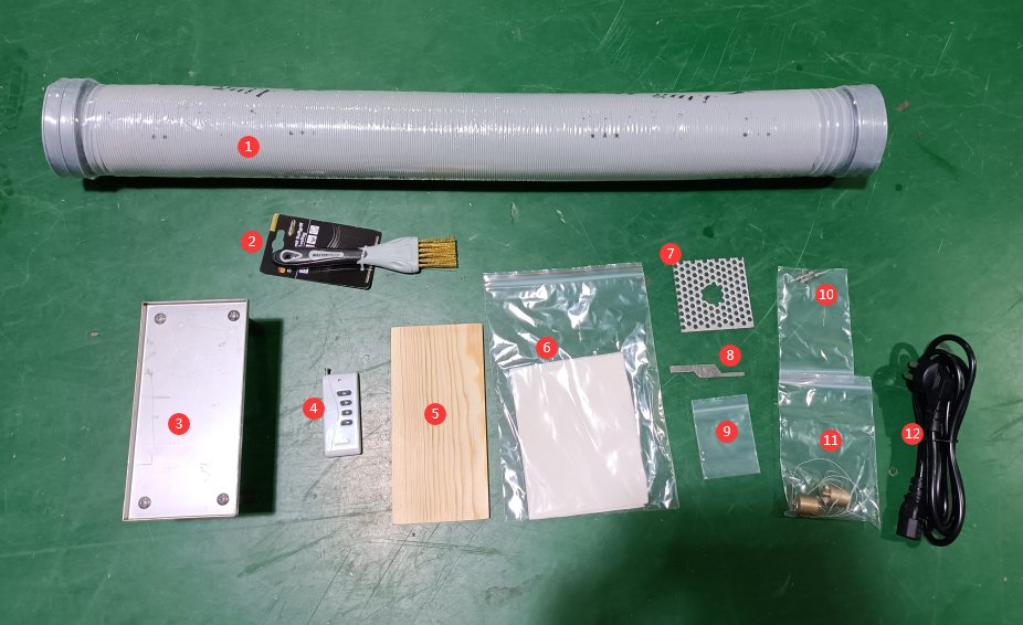
Glow-wire Test Apparatus main unit: 1 unit.
Standard accessories are as follows:① Exhaust pipe, ② Metal brush, ③ Collection tray, ④ Remote control, ⑤ Pine board, ⑥ Test paper, ⑦ Sample clamp, ⑧ Gauge, ⑨ Silver foil, ⑩ Spare fuse, ⑪ Weights, ⑫ Power cord.
Note: Batteries are prohibited items and may not be shipped with the product. If you need to use the remote control, please purchase batteries specifically designed for it on your own.
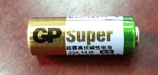
Пульт дистанционного управления выполняет те же функции, что и сенсорные кнопки; пользователи могут выбрать, использовать пульт или нет.
Ссылки для скачивания цифрового руководства пользователя, гарантийного талона и других документов были отправлены вам по электронной почте. Пожалуйста, скачайте их как можно скорее. Если вы пропустили письмо, пожалуйста, свяжитесь с нами, чтобы запросить ссылки для скачивания еще раз.
1.3 Описание конструкции оборудования
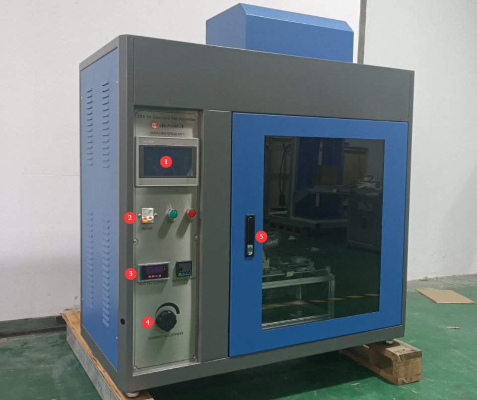
1.3.1 Вид спереди испытательной камеры
① Touchscreen; ② Power controls, circuit breaker, power-on switch, and power on/off buttons; ③ Heating current display and real-time display of the heating wire temperature; ④ Heating current adjustment knob; ⑤ Test chamber door.
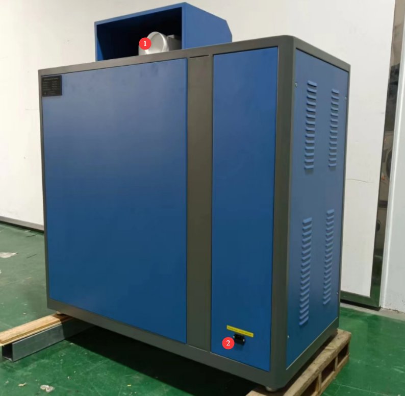
1.3.2 Задняя часть испытательной камеры
① Exhaust vent, 100 mm in diameter, securely connected to an exhaust duct that extends to the outside; ② Power outlet.
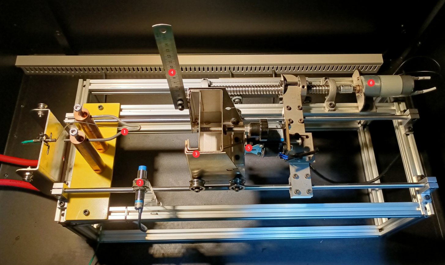
1.3.3 Внутри испытательной камеры
① Glow wire and its thermocouple; ② Proximity switch, used to control the final position of the sample carriage; ③ Sample carriage, used to mount the sample; ④ Steel ruler, used to measure the height of the flame if the sample catches fire; ⑤ Magnet assembly, used to control the 7-mm pressure-limiting depth; ⑥ Motor, used to drive the sample carriage.
2. Меры предосторожности.
2.1 Электробезопасность
2.1.1 Подключение питания
Однофазное питание 220 В; розетки должны соответствовать стандартам безопасности, иметь надлежащее заземление и номинальный ток, соответствующий номинальной мощности оборудования (рекомендуется установить отдельный автоматический выключатель).
We recommend using a regulated power supply; voltage fluctuations can cause fluctuations in the heating current of the heating element, resulting in unstable heating element temperatures.
2.1.2 Технические характеристики заземления
Оборудование должно быть надежно заземлено, при этом сопротивление заземления должно быть ≤4 Ом. Не используйте газовые трубы, неметаллические водопроводные трубы или нейтральный провод в качестве замены заземляющего провода. После завершения заземления измерьте сопротивление заземления с помощью тестера сопротивления заземления. Подача питания допускается только после подтверждения соответствия требованиям, чтобы предотвратить поражение электрическим током, неисправности оборудования или ошибки измерений, вызванные плохим заземлением.
2.1.3 Противопоказания
Перед подключением проводов, осмотром или техническим обслуживанием оборудования необходимо отключить основное электропитание оборудования и убедиться в отсутствии остаточного напряжения.
Во избежание поражения электрическим током не следует нажимать на выключатель питания, сенсорный экран или кнопки приборов мокрыми руками;
Не размещайте внутри электрощита посторонние предметы (например, инструменты или бумагу), чтобы предотвратить короткое замыкание или повреждение компонентов из-за пыли или других посторонних предметов;
Не подключайте и не отключайте шнуры питания или сигнальные кабели во время работы оборудования, чтобы предотвратить короткие замыкания, которые могут повредить контроллер или электрические компоненты.
2.2 Эксплуатационная безопасность
Во время работы оборудования, Непрофессионалам запрещается разбирать или ремонтировать данное устройство. it. In the event of a malfunction, contact after-sales personnel or operate the equipment under the guidance of a technician;
Во время испытаний дверца высокотемпературной камеры должна быть закрыта. Наблюдайте за процессом испытаний через смотровое окно камеры, чтобы избежать ожогов от высокотемпературного излучения или искр от горящих материалов.
Do not adjust mechanical components such as proximity switches or weights while the equipment is in operation;
In the event of a malfunction or abnormality, immediately stop the test and troubleshoot the problem (see “Chapter 9: Troubleshooting and Handling Common Malfunctions”). Do not force the equipment to start up; operating the equipment before the problem is resolved may cause further damage to the equipment;
Do not open the control cabinet door while the equipment is running to avoid touching the high-voltage components inside, which could result in electric shock;
Не разбирайте основные компоненты без разрешения. Модификация оборудования аннулирует гарантию и может привести к инцидентам, связанным с безопасностью.
Do not place heavy objects (such as tools, accessories, etc.) on top of the equipment to avoid damaging the equipment panel or impairing heat dissipation;
2.3. Экологическая безопасность
2.3.1 Требования к установке
Оборудование необходимо установить в комната с кондиционером, где Температура окружающей среды поддерживается в пределах от 5°C до 25°C, а относительная влажность составляет ≤85%. При высокой влажности окружающей среды вблизи дверцы оборудования и испытательных портов может образовываться конденсат; в таких случаях следует улучшить вентиляцию помещения или использовать осушитель воздуха.
Место установки должно быть свободно от высокой концентрации пыли, коррозионных газов (таких как диоксид серы и хлор), а также легковоспламеняющихся или взрывоопасных атмосфер. Не допускайте попадания прямых солнечных лучей на оборудование, чтобы предотвратить коррозию корпуса и износ электрических компонентов.
Хранение легковоспламеняющихся и взрывоопасных материалов (таких как спирт, бензин и т. д.) в зоне испытаний строго запрещено во избежание риска пожара или взрыва;
Рабочая зона оборудована огнетушителями (пороховыми или углекислотными), и операторы знакомы с правилами их использования;
Keep the equipment away from areas with significant fluctuations in ambient temperature, such as near vents or room entrances, to prevent the temperature control accuracy from being affected;
Держитесь подальше от источников сильных магнитных и электрических полей (таких как крупные электродвигатели и высоковольтное оборудование).
2.3.2 Требования к пространству
Расстояние между корпусом оборудования и стеной, а также окружающими конструкциями (такими как другое испытательное оборудование и стеллажи)., must be at least 1000 mm to facilitate maintenance;
Минимум 2000 мм of space must be left clear around the equipment door to ensure that the door can be opened in any direction, facilitating the placement and removal of samples.
2.3.3 Горизонтальное размещение
The device must be placed on плоская поверхность. Use a level to ensure the device is level: Place the level on the top surface of the device and make sure the bubble is centered. Note: The device has four adjustable feet that can be used to level it. After leveling the device, ensure that all four feet are firmly in contact with the floor.
If the equipment is tilted, it may cause the sample cart to run poorly, affecting the testing process and the equipment’s service life.
Другие 2.4
По вопросам, не охваченным данным руководством, пожалуйста, проявляйте осторожность или свяжитесь с нами.
3. Введение в программу сенсорного экрана
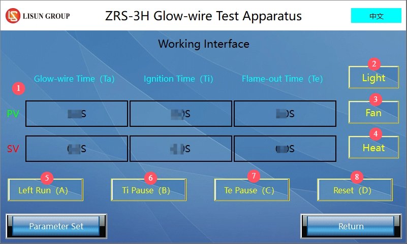
3.1 Пользовательский интерфейс
① PV displays the current time; SV displays the set time; ② Lighting: Used to turn on the lighting inside the test chamber for easier observation; ③ Fan: Used to exhaust smoke generated inside the test chamber after the test is complete; ④ Heating: Used to heat the glowing wire; ⑤ Left (A): Used to start the test;⑥ Ignition Time Pause (B): Used to record the ignition time (Ti); ⑦ Extinction Time Pause (C): Used to record the flame extinction time (Te); ⑧ Reset (D): Press after the test is complete or before starting the next test to clear the test data. Note: The four buttons (A, B, C, and D) can also be controlled using a remote control.
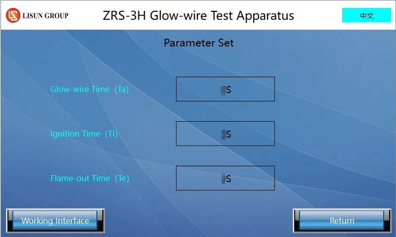
3.2 Интерфейс настройки параметров
Used to set the glow time (Ta), ignition time (Ti), and flame extinction time (Te).
4. Подготовка к тесту
4.1 Внешняя среда
In accordance with the requirements of the GB/T 5169.10 (IEC 60695-2-10) standard, adjust the ambient temperature to 23±2°C and the relative humidity to 50±5% to prevent environmental factors from affecting the test results. Note: The temperature and humidity requirements for the equipment’s storage environment differ from those for its operating environment.
4.2 Предварительная обработка образцов
In accordance with GB/T 5169.10-13 (IEC 60695-2-13), test specimen dimensions: Prepare specimens in accordance with the standard; typical dimensions are 100 mm × 100 mm × thickness (based on the actual thickness of the material in use, not to exceed 13 mm).
Number of specimens: At least 3 specimens per test group, which must be prepared under the same conditions.
Conditioning: The test specimens must be left in an environment at 23±2°C and 50±5% humidity for at least 24 hours to ensure they are in a stable condition.
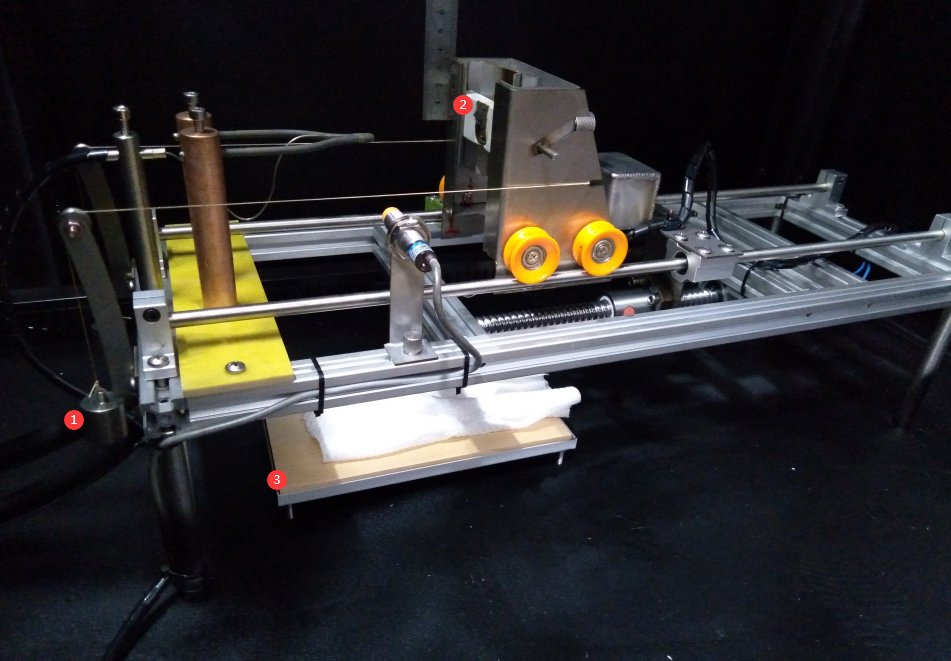
4.3 Internal Environment
① Pass the pull ropes of the two weights over the trolley, then hang them on the two pulleys, respectively; ② Install the specimen; if necessary, use a metal mesh specimen holder to adjust the specimen’s position, ensuring that the contact point of the glowing wire is in the center of the specimen and that the contact area meets the standard requirements;③ Place the specimen tray, the pine board, and the special test paper directly beneath the U-shaped tip of the glowing wire.
4.4 Adjusting the Position of the Proximity Switch
Adjust the position of the proximity switch according to the sample. You can first move it to the right a short distance to ensure safety. First, press the “Reset” button, then tap “Left” on the touchscreen, and the cart will automatically move to the left.
When the carriage reaches the proximity switch, it stops. If the position is not ideal, tap “Reset” on the touchscreen, and the carriage will automatically move away. Then, after readjusting the proximity switch’s position, tap “Move Left” again. Repeat this process until the cart finally stops at the desired position. The final position should be: the sample is in contact with the hot wire, and the distance between the hot wire and the sample cart is 7 mm. This distance can be measured with a gauge when the cart is at its final position, as shown in the figure below:
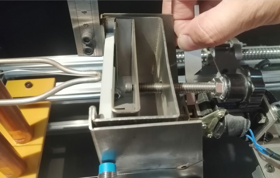
Note 1: Pay close attention to the position of the two weights. Throughout the entire process, the weights must not come into contact with any other objects and must remain suspended steadily in the air at all times. If this is not the case, adjust the position of the weights or the length of the pull rope.
Note 2: After adjusting the proximity switch position, tap “Reset” on the touchscreen to return the carriage to its initial position, then wait for the test to begin. Note: If you need to test samples of other shapes and sizes later, you may need to readjust the proximity switch position.
5. Operating Procedures for the Glowing Wire Test
5.1 Настройки параметров тестирования
In accordance with the requirements of the GB/T 5169.11 (IEC 60695-2-11) standard, make the following settings.
Glow time (Ta): Typically 30 seconds; Ignition time (Ti): Same as glow time, 30 seconds; Flame extinction time (Te): 60 seconds.
If users are referring to other standards or conducting non-standard tests, they may adjust the settings as needed.
5.2 Adjusting the Glow Wire Temperature
Make sure the current adjustment knob is set to the minimum position to avoid a sudden high-current surge.
Tap “Heat” on the touchscreen. ① Then slowly turn the current knob clockwise. ② The display shows the current heating current, and ③ the current temperature of the heating element. Note: Please adjust the current knob slowly and wait patiently for the heating element to stabilize at the specified temperature.
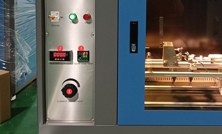
The figure below shows the relationship between current and the temperature of a glowing wire:
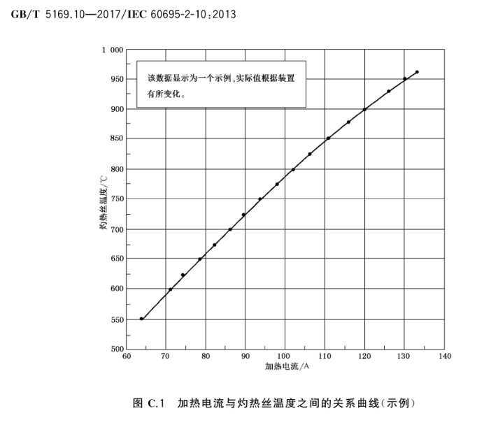
In practice, the current may vary slightly depending on the specific operating environment; however, this does not affect the operation of the equipment or the test results. Common test temperatures are 550°C, 650°C, 750°C, 850°C, and 960°C. Please select the appropriate temperature based on the material’s required flame resistance rating.
5.3 Эксплуатационные испытания
Make sure the test chamber door is closed. Click “Reset (D)” to clear the historical test data. Click “Left (A)” to move the sample cart with the samples to the left.
When the sample cart reaches the proximity switch, the sample comes into contact with the incandescent wire, and the test begins. The incandescence time (Ta), ignition time (Ti), and flame extinction time (Te) are all timed simultaneously.
If the sample ignites within the 30-second heating period, immediately click “Ignition Time Pause (B)” and record the ignition time Ti. Observe the combustion: the height of the flame and whether any burning droplets ignite the test paper, and manually record the relevant observations.
After the 30-second heating period is complete, the sample carrier automatically disengages from the heating wire, and the “Heat” button automatically pops up, stopping the heating process. As soon as the sample flame goes out, immediately click “Flame Extinction Time Pause (C)” to record the flame extinction time (Te).
Note 1: If the sample does not ignite during the test, there is no need to click “Ignition Time Pause (B)” or “Extinction Time Pause (C),”
Note 2: If the flame continues to burn beyond the set value of Te (the flame extinguishing time) of 60 seconds, manual intervention is required to extinguish the fire, and this must be recorded.
Note 3: According to the standard’s explanatory notes, the sample’s flame must extinguish within 30 seconds after the sample leaves the incandescent wire for the test to be considered passed. Example: If the flame extinction time (Te) recorded during the glowing wire test is 45 seconds—meaning the sample’s flame extinguished 15 seconds after the sample left the glowing wire—this meets the standard requirements.
6. Процедуры после испытаний
6.1 Эксплуатация оборудования после испытаний
6.1.1 Безопасное обращение
Turn the current control knob to the minimum setting.
After the test is complete, keep the exhaust fan running for at least 10 minutes to ensure that all exhaust gases are completely removed from the chamber.
Do not open the chamber door immediately; wait until the temperature drops below 50°C before opening the door to remove or place samples.
6.1.2 Очистка оборудования
Wipe the interior walls of the test chamber with a dry cloth to remove any residual soot or drips (if there are stubborn stains, wipe them with a neutral detergent, then rinse with clean water).
Cleaning the heating element: Gently brush away any oxidation or residue from the surface with a metal brush, taking care not to apply too much force, which could cause the heating element to deform.
Clean the sample tray, pine boards, and test paper: Replace any test paper that has been ignited or contaminated; if the pine boards show signs of burning, replace them immediately.
6.2 Запись и организация экспериментальных данных
Test records are archived в соответствии с standard GB/T 5169.13 (IEC 60695-2-13).
Key Data: Heating Temperature, Glow Time, Ignition Time (Ti), and Flame Extinction Time (Te).
Observation Record: Whether the specimen ignited, flame height, duration of combustion, whether dripping material ignited the test paper, and the condition of the specimen after combustion (e.g., whether it charred or cracked).
6.3 Подготовка проб
Remove the test specimens after testing and store them according to hazardous waste classifications (if the specimens contain toxic or hazardous substances, they must be sealed and disposed of separately).
Set aside a portion of the test specimens for subsequent re-inspection or as traceability samples, and label them with the test number and date.
6.4 Хранение оборудования
6.4.1 Требования к краткосрочному хранению
Если оборудование используется ежедневно, после завершения очистки после каждого теста никаких дополнительных действий не требуется.
6.4.2 Требования к долговременному хранению
Если устройство не будет использоваться в течение длительного периода времени (более одного месяца), пожалуйста, отсоедините шнур питания и накройте устройство пылезащитным чехлом, чтобы предотвратить скопление пыли.
Для предотвращения износа электрических компонентов (таких как конденсаторы и контакторы) устройство следует включать раз в месяц всего на полчаса.
7. Калибровка температуры
7.1 Подготовка к калибровке
7.1.1 Условия калибровки
Environmental Requirements: Temperature 23±2°C, humidity 50±5%, no airflow disturbances.
Equipment Status: Power on the equipment and allow it to warm up for 30 minutes to ensure stable operation; the heating wire is clean and free of residue, and the thermocouple is securely connected.
Calibration tools: Standard silver foil (0.1 mm thick, purity ≥ 99.9%), stainless steel gauge.
7.1.2 Основа калибровки
In accordance with the requirements of the GB/T 5169.12 (IEC 60695-2-12) standard, the instantaneous melting of a silver foil at 960°C is used as the basis for calibration.
7.2 Процедура калибровки
Open the test chamber door and place the silver foil flat directly above the front end of the U-shaped tip of the incandescent wire, ensuring that the silver foil makes good contact with the incandescent wire and is not suspended in the air. Then close the test chamber door.
Tap “Heat” on the touchscreen, slowly turn the current adjustment knob to gradually increase the temperature, and observe the condition of the silver foil.
When the temperature reaches 960°C, observe whether the silver foil melts instantly; if it does not melt, continue to heat it slowly and record the temperature at which the silver foil melts.
7.3. Действия при отклонении температуры во время калибровки
If the temperature displayed when the silver foil melts deviates by ≤±5°C from 960°C, the calibration is considered acceptable; if the deviation exceeds ±5°C, the position of the thermocouple must be adjusted (ensuring that the thermocouple probe is in close contact with the hot wire).
Repeat the calibration procedure after making adjustments until the deviation meets the requirements; if the device still fails to meet the requirements after multiple adjustments, replace the thermocouple or the hot wire.
Note: The glow wire and thermocouple are consumable items; replace them promptly if their parameters are incorrect. Severe open flames during testing can also shorten the service life of the glow wire and thermocouple.
8. Текущее обслуживание
|
Цикл обслуживания |
Проекты технического обслуживания |
Операции по техническому обслуживанию |
|
После каждого теста |
Очистка оборудования |
1. Протрите внутреннюю и внешнюю поверхности испытательной камеры, смотровое окно и крепления; 2. Удалите все капли и сажу с поддона для сбора капель. |
|
Раз в неделю |
Обслуживание подшипников |
Для обеспечения плавной работы подвижных частей протрите направляющую линейного подшипника тканью, смоченной растительным маслом. |
|
Раз в 3 месяца |
Калибровка температуры |
Verify that the temperature displayed when the silver foil melts deviates by no more than ±5°C from 960°C. Replace the hot wire and thermocouple if necessary. |
|
Раз в 6 месяца |
Осмотр электрической системы |
1. Убедитесь в надежности подключения силовых проводов и клемм заземления; 2. Замените изношенные предохранители; 3. Проверьте работоспособность системы зажигания. |
|
Раз в год |
Comprehensive Maintenance of Calibration Equipment |
Contact a supplier or a third-party testing organization to arrange for professional testing and calibration |
9. Поиск и устранение распространенных проблем
9.1 Power Supply and Startup Faults
9.1.1 Symptom: The device will not power on
Possible causes: Damaged power cord, loose plug connection, blown fuse, or faulty power switch.
Процедура:
Check that the power cord is in good condition and that the plug is securely connected; try plugging it into a different outlet. Open the device’s fuse box and replace the fuse with a spare one (of the same specification). If the fuse blows again after replacement, contact a professional to inspect the internal circuitry. If the power switch does not respond, it may be damaged and will need to be replaced.
9.1.2 Symptom: No display on the touchscreen
Possible causes: Power supply issue with the touchscreen, screen damage, or loose internal wiring.
Процедура:
Check the power cord connection to ensure the power supply is working properly; restart the device to see if the issue is resolved. If the screen still does not display anything, contact the manufacturer to replace the touchscreen or repair the internal wiring.
9.2 Temperature-Related Failures
9.2.1 Symptom: The temperature cannot reach the setpoint
Possible causes: Improper current adjustment, aging of the heating wire, misalignment of the thermocouple, or a faulty heating element.
Процедура:
Turn the current adjustment knob clockwise to increase the heating current (refer to the temperature-current curve) and observe the temperature change; check the hot wire for breaks or severe oxidation. If so, replace the heating wire; adjust the position of the thermocouple to ensure the probe is in close contact with the heating wire, with no gaps. If the thermocouple is damaged, replace it with a Type K armored thermocouple.
9.2.2 Symptom: Excessive temperature fluctuations (exceeding ±5°C)
Possible causes: unstable voltage, interference from ambient airflow, malfunctioning exhaust fan, or poor thermocouple contact.
Процедура:
It is recommended to use a regulated power supply. Close the doors and windows in the test area to prevent airflow from affecting the test; ensure that the exhaust fan is turned on only after the test is complete; check the thermocouple connections and tighten any loose terminals; clean any dirt or debris from the surface of the thermocouple probe.
9.3 Mechanical Malfunctions
9.3.1 Symptoms: The cart cannot move to the left or moves away on its own
Possible causes: Incorrect proximity switch position, weight entanglement, jammed sample holder, or motor failure.
Процедура:
Readjust the position of the proximity switch to ensure proper sensitivity; remove any copper wire wrapped around the weights to ensure smooth suspension; check the sample rack for any foreign objects causing a jam, remove them, and then manually push the sample rack to test its smooth operation; if it still does not operate, there may be a fault with the drive motor; please contact us for repair.
9.3.2 Failure Symptom: Abnormal contact pressure between the hot wire and the specimen
Possible causes: Deviation in the weight of the calibration weights, a jammed pulley, or a misalignment of the sample holder.
Процедура:
Calibrate the weight of the calibration mass to ensure it is 0.95 ± 0.1 N; check that the pulley runs smoothly and add lubricant (if necessary); readjust the position of the sample holder and use a stainless steel gauge to measure the compression depth, ensuring it is 7 mm.
9.4 Другие неисправности
9.4.1 Symptom: A large amount of odor or smoke generated during the test cannot be vented
Possible causes: Clogged exhaust duct, malfunctioning exhaust fan, or poor ventilation.
Процедура:
Clean out dust and grease buildup from the exhaust duct to ensure it remains clear; check that the exhaust fan is operating normally; if it is malfunctioning, repair or replace it.
If it still fails the test, the thermocouple or hot wire must be replaced.
Note: The glow wire and thermocouple are consumable parts; replace them promptly if their parameters are incorrect. The presence of intense open flames during testing can also shorten the service life of the glow wire and thermocouple.