
 Английский
 中文简体
中文简体 Русский
 Español
 Português
 Türkçe
 العربية
 Deutsch
 Polski
 Italiano
 Français
 한국어
한국어 ไทย
ไทย Tiếng Việt
 日本語
日本語





























Испытательная камера композитного солевого тумана
Руководство пользователя
Применимый LISUN модели: YWX/Q-010X,YWX/Q-016X,YWX/Q-020X,YWX/Q-250X
1. Распаковка и знакомство с оборудованием.
1.1 Основные технические характеристики
|
LISUN Модель |
YWX/Q-250X |
YWX/Q-750X |
YWX/Q-010X |
YWX/Q-016X |
YWX/Q-020X |
|
Размеры студии |
× × 900 600 500 |
× × 1100 750 500 |
× × 1200 800 500 |
× × 1600 1000 600 |
× × 2000 1000 600 |
|
Размеры внешней коробки |
× × 2160 1100 1300 |
× × 2360 1250 1300 |
× × 2460 1300 1350 |
× × 2860 1500 1450 |
× × 3260 1500 1450 |
|
Объем лабораторных работ |
270L |
412L |
480 л |
960L |
1200 л |
|
Емкость солевого бака |
25 л |
30L |
30L |
35L |
40L |
|
Емкость резервуара для чистой воды |
30L |
35L |
35L |
40L |
50L |
|
Электропитание |
Трехфазное переменное напряжение 380 В/50 Гц (60 Гц доступно по запросу) |
||||
|
10.0 кВт |
12.0 кВт |
12.5 кВт |
16.0 кВт |
18.5 кВт |
|
|
Как открыть крышку |
Manual Lid Opening |
Газовые пружины из нержавеющей стали |
цилиндр |
||
|
Диапазон лабораторных температур |
15–65 ° C |
||||
|
Saturated Drum Temperature Range |
RT (Room Temperature) ~ 70°C |
||||
|
Относительная влажность |
30%–98% RH (±3%, adjustable; see the “Temperature and Humidity Control Range” chart) |
||||
|
Скорость осаждения солевого тумана |
1–2 mL/80 cm²/h |
||||
|
Методы испытаний |
Programmable Spray, Damp Heat, Drying, Standard Climate |
||||
1.2 Распаковка и проверка содержимого
1.2.1 Распаковка и визуальный осмотр
При распаковке оборудования обращайтесь с ним осторожно, чтобы избежать ударов по основному блоку. После распаковки сначала осмотрите корпус оборудования, стеклянную дверцу камеры распыления, сенсорный экран и другие компоненты на наличие повреждений, деформаций или царапин.
Проверьте все соединения оборудования (питание, воздухозабор, выхлоп, слив и т. д.), чтобы убедиться в их исправности и отсутствии ослабленных соединений, засоров или повреждений.
If you discover that the equipment or any accessories are damaged or deformed, do not power on the device; контакт LISUN обслуживание клиентов немедленно.
1.2.2 Тип хоста
1 main unit of a Composite Salt Spray Test Chamber.
1 воздушный компрессор. Примечание: его можно приобрести у LISUN или приобретаются самостоятельно. При самостоятельном приобретении следует руководствоваться следующими техническими характеристиками: емкость воздушного резервуара 55 л; расход воздуха 0.6 м³/мин; максимальное давление: 0.8 МПа. Воздушный компрессор должен быть оборудован маслоотделителем для предотвращения попадания масла и влаги из сжатого воздуха в воздуховоды оборудования, что может привести к засорению форсунок или коррозии компонентов.
1.2.3 Расходные материалы и аксессуары
① Graduated cylinder; ② Sample holder, V-notch, and O-shaped rod; ③ Test salt: analytically pure sodium chloride, 500 g × 2; once used up, you may purchase more on your own or contact LISUN Customer Service; ④ Spare quartz glass nozzles.

Ссылки для скачивания цифрового руководства пользователя, гарантийного талона и других документов были отправлены вам по электронной почте. Пожалуйста, скачайте их как можно скорее. Если вы пропустили письмо, пожалуйста, свяжитесь с нами, чтобы запросить ссылки для скачивания еще раз.
1.3 Описание конструкции оборудования
1.3.1 Вид спереди испытательной камеры
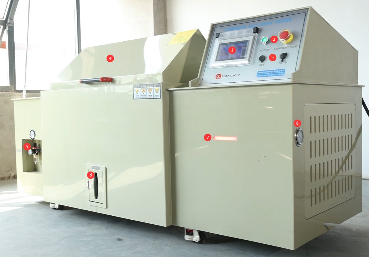
① Touchscreen; ② Power switch and emergency stop button; ③ USB port for exporting test curves; RS port (for backup); ④ Test chamber lid; ⑤ Air compressor connection and pressure regulator;⑥ Measuring cylinder, connected to the mist collector inside the test chamber; used when measuring rainfall. The number of funnels and measuring cylinders varies depending on the size of the test chamber; ⑦ Equipment status indicator light: red for alarms, yellow for standby, and green for operation; ⑧ Refrigerant pressure gauge.
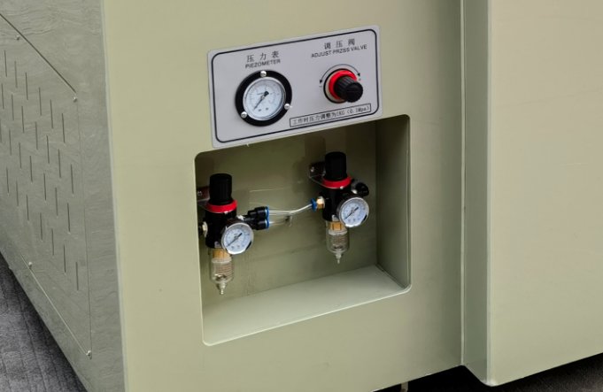
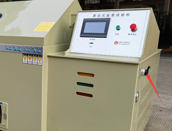
If your test chamber uses a pneumatic cylinder to open the lid, there will be an additional pressure regulator at the air compressor connection, and the unit will also have a handle for opening and closing the test chamber lid, as shown in the figure below:
1.3.2 Задняя часть испытательной камеры
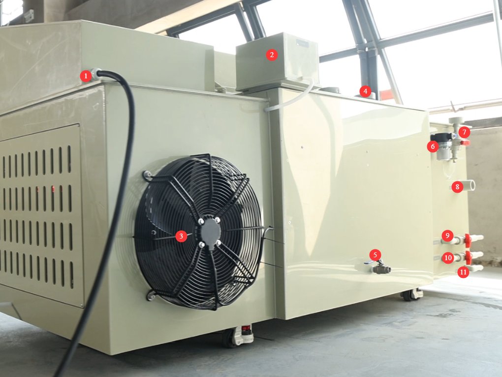
① Power cord; ② Gauze tray water tank; ③ Condenser exhaust fan; ④ Circulation fan (operates when controlling temperature and humidity); ⑤ Humidifier tray drain valve (remains closed during normal operation); ⑥ Pure water tank automatic refill port; ⑦ Saturation tank manual fill port;⑧ Mist exhaust port; ⑨ Brine tank drain pipe; ⑩ Pure water tank drain pipe; ⑪ Overflow port.
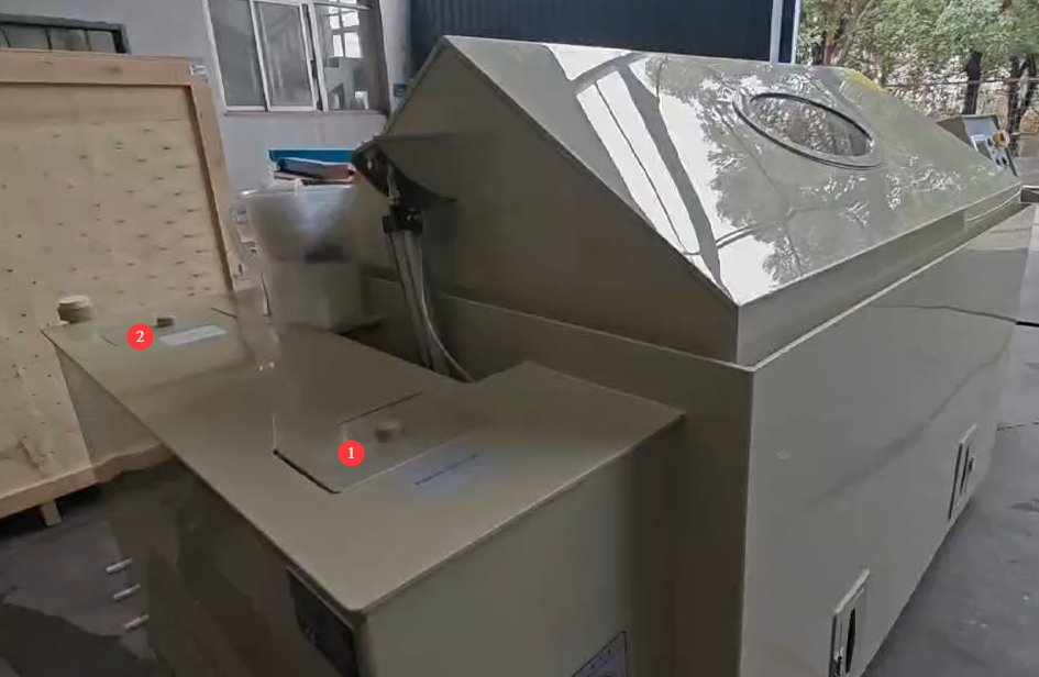
1.3.3 Side of the Test Chamber
① Brine tank; ② Pure water tank.
1.3.4 Внутри испытательной камеры (туманной камеры)
① Spray tower and nozzles; the number depends on the size of the test chamber; ② Brine level control device; ③ Temperature and humidity probes; brine hoses and saturated tank hoses—these hoses contain filters that need to be cleaned over time; ④ Mist collector; ⑤ Steam outlet for humidity testing;⑥ Fan outlet; ⑦ Air inlet for defogging—during defogging, compressed air from the air compressor enters the test chamber through this inlet; ⑧ Sealing water trough for the test chamber lid.
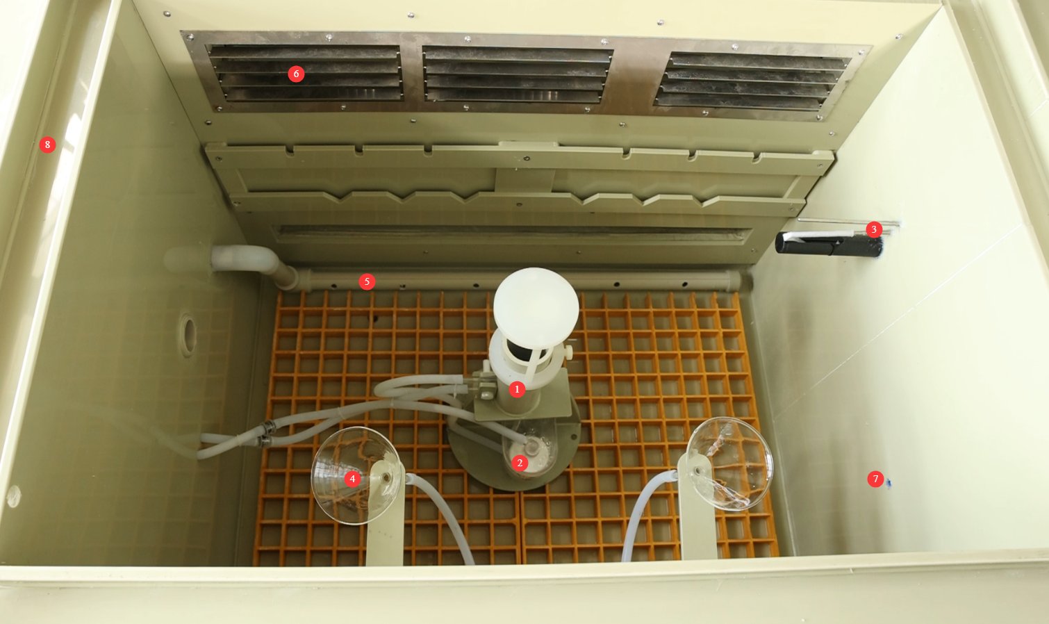
Note: If your test chamber uses a pneumatic cylinder to open the lid, you must turn on the power and the air compressor, and use the cylinder to open the lid before you can see inside the test chamber.
2. Меры предосторожности.
2.1 Электробезопасность
2.1.1 Подключение питания
A 380V three-phase, five-wire power supply must be used, and the power rating must be matched to the specific model. The wire specifications for the corresponding equipment models must meet the following requirements: YWX/Q-250X ≥ 2.5 mm²; YWX/Q-750X, YWX/Q-010X и YWX/Q-016X ≥ 4.0 mm²; YWX/Q-020X ≥ 6.0 mm². A dedicated circuit must be used for power supply, and it is recommended to install a separate circuit breaker.
2.1.2 Технические характеристики заземления
Grounding must be performed in accordance with the standards for three-level grounding systems, with a grounding resistance of ≤50 Ω; a dedicated grounding wire must be used to connect to the ground.
It is strictly prohibited to connect grounding wires to gas lines, non-metallic water pipes, heating pipes, or other flammable or explosive facilities to avoid the risk of electric shock or fire.
2.1.3 Противопоказания к проведению процедуры
Before connecting, servicing, or replacing parts on the equipment, you must disconnect the power supply before proceeding.
Не прикасайтесь к разъему питания, сенсорному экрану или другим электрическим компонентам мокрыми руками. Во избежание поражения электрическим током избегайте скопления воды вокруг устройства.
If any abnormalities occur while the equipment is in operation—such as electrical leakage, unusual noises, or smoke—immediately disconnect the power supply and contact a professional for repair; do not attempt to disassemble the equipment yourself.
2.2 Эксплуатационная безопасность
2.2.1 Ограничения на образцы для испытаний
This device is intended only for testing non-flammable, non-explosive, and non-radioactive solid or flexible materials (such as metal coatings, plastic parts, electronic component housings, etc.).
If the sample contains volatile components (such as organic solvents or corrosive gases), you must consult the equipment compatibility instructions in advance or conduct a preliminary test with a small sample to confirm that there are no safety risks (such as corrosion of equipment components or the generation of toxic gases). Otherwise, do not place the sample in the equipment.
2.2.2 Правильно подсоедините выхлопную трубу
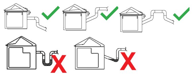
Salt fog is corrosive; the exhaust pipe must be connected to the outdoors or a dedicated drainage system. It must not be discharged indoors or connected to a standard sewer system.
The mist exhaust pipe must remain unobstructed, free of kinks or blockages, and must not include a P-trap; otherwise, salt spray condensate will accumulate inside the pipe, blocking the exhaust channel and affecting test results and equipment safety. See the diagram below:
2.2.3 Запрещенное поведение
While the equipment is in operation, non-professionals are prohibited from disassembling or repairing it. In the event of a malfunction, contact customer service or follow the instructions of a technician.
If the equipment triggers an alarm, immediately stop the test and troubleshoot the problem (see “Chapter 6: Troubleshooting and Resolution of Common Problems”). Do not force the equipment to restart; operating it before the problem is resolved may cause further damage to the equipment.
Do not open the test chamber lid until the test is complete and the defogging process has finished, to prevent direct contact between the salt spray and human skin.
Do not disassemble core components such as nozzles, temperature probes, heating elements, and liquid level sensors without authorization. Do not modify the equipment’s electrical, pneumatic, or structural systems. Failure to comply will void the equipment’s warranty and may result in safety incidents.
2.3. Экологическая безопасность
2.3.1 Требования к установке
Температура окружающей среды: 5–25 °C. Избегайте чрезмерно высоких температур, которые могут повлиять на стабильность системы регулирования температуры в испытательной камере, и чрезмерно низких температур, которые могут повлиять на эффективность нагрева.
Относительная влажность: ≤85% RH. Для предотвращения коротких замыканий в электрических компонентах оборудования, вызванных влагой, окружающая среда должна быть сухой.
Прочие требования: Отсутствие прямых солнечных лучей (во избежание колебаний температуры в камере солевого тумана); отсутствие сильных электромагнитных полей (например, от трансформаторов напряжения или крупных электродвигателей, чтобы избежать помех для системы управления); отсутствие сильных воздушных потоков (например, прямого потока воздуха из вентиляционных отверстий кондиционеров, который может повлиять на распределение солевого тумана); диапазон атмосферного давления: 86–106 кПа.
2.3.2 Требования к пространству
The equipment must be placed on a level surface; use a level to ensure the unit is stable (tilting may cause uneven salt spray distribution and liquid leaks).
Allow sufficient space around the equipment: ≥1500 mm on the left, right, and rear sides (to facilitate piping and cable connections, liquid refills, and maintenance), and ≥2000 mm at the front (to allow access to the control panel door and touchscreen).
Другие 2.4
По вопросам, не охваченным данным руководством, пожалуйста, проявляйте осторожность или свяжитесь с нами.
3. Подготовка к операции
3.1 Подключение кабельных каналов
3.1.1 Подключение шнура питания
См. 2.1.
3.1.2 Подключение выхлопной трубы
Используйте выхлопной шланг, входящий в комплект поставки. LISUN. If you provide your own exhaust hose, please use a hose with an inner diameter of 50 mm and connect it as described in Section 2.2.2.
3.1.3 Подключение канализационных труб
For the brine tank water supply line, the purified water tank drain line, and the overflow outlet, use non-metallic tubing (such as PPR tubing) with an inner diameter of 20 mm. Connect one end to the drain port on the back of the unit and the other end to the sewer line. The tubing must be installed at a slope to ensure proper drainage.
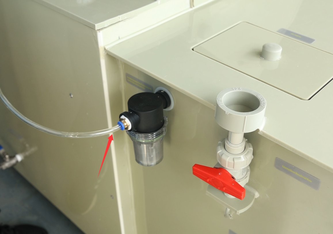
3.1.4 Connection of the Automatic Water-Filling Port on the Pure Water Tank
Connect to a purified water source under pressure using an 8mm-diameter water tube (water quality must be pH 6.5–7.5; do not use tap water or bottled water to prevent scale buildup), The inlet pressure must be ≥0.1 MPa. Keep the valve open at all times to automatically fill the purified water tank, which will then automatically replenish the humidifier chamber and the saturation tank.
3.1.5 Подключение воздушного компрессора и регулировка входного давления
Используйте воздушный шланг диаметром 8 мм, подсоединив один конец к выходному отверстию воздушного компрессора, а другой — к входному отверстию на задней панели устройства. Отрегулируйте ручку, показанную на рисунке ниже, чтобы установить давление воздуха на уровне 0.2 МПа для распыления.
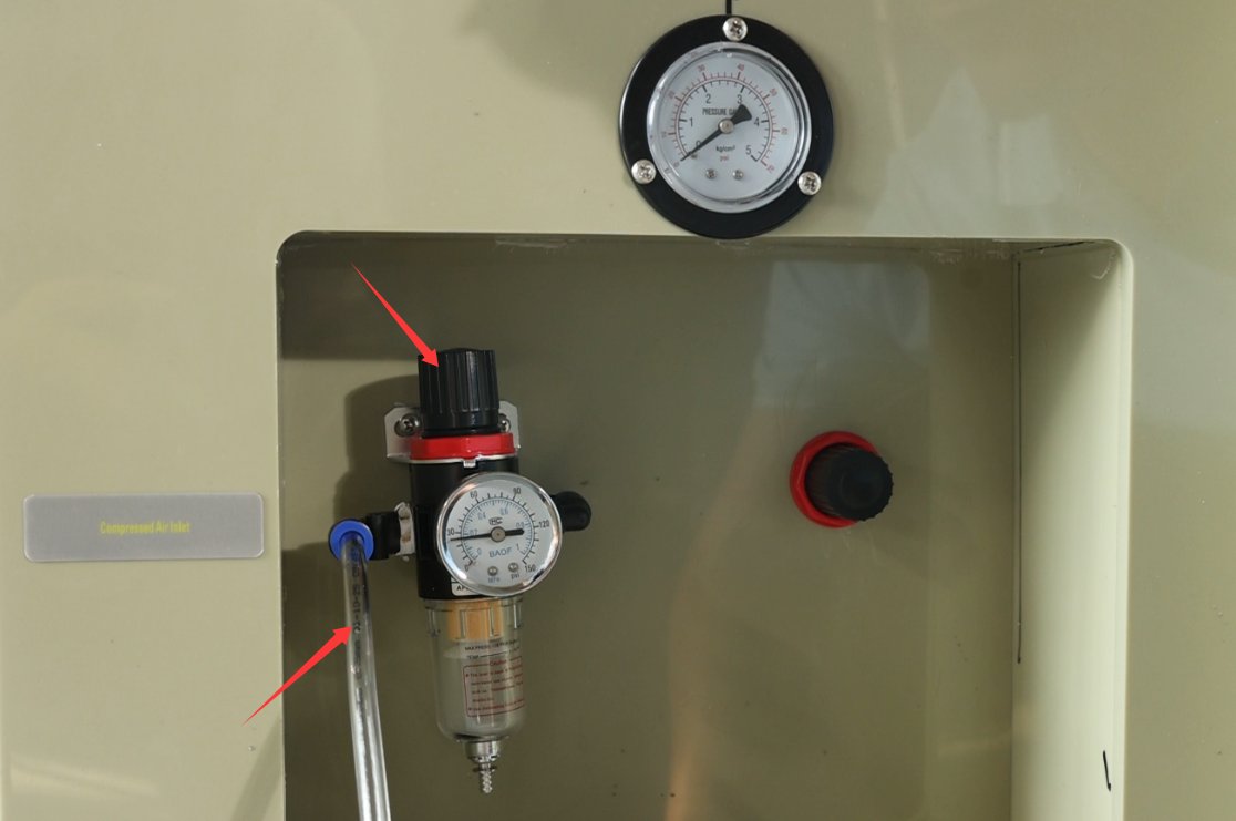
Если в вашей камере для солевого тумана используется пневматический цилиндр для открытия крышки, то будет два регулятора давления, как показано на рисунке ниже: ① Первый подает воздух в цилиндр и должен быть установлен на 0.4 МПа. ② Второй предназначен для распыления и должен быть установлен на 0.2 МПа.
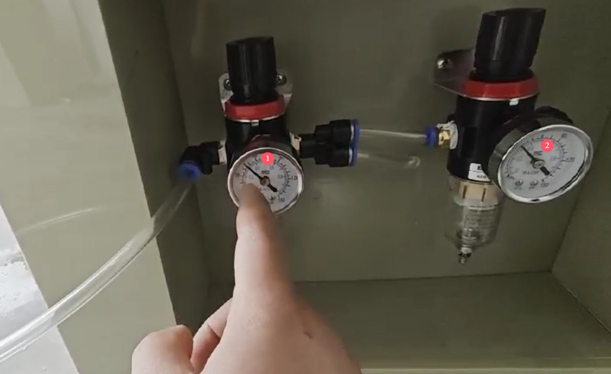
После внесения корректировок необходимо контролировать систему и убедиться в стабильности давления воздуха; нестабильное давление воздуха может повлиять на эффективность распыления.
3.2 Checking the Status of the Test Chamber
3.2.1 Очистка испытательной камеры
During transportation, it is inevitable that debris or dust will enter the test chamber. Before using the equipment for the first time, please clean the interior of the test chamber, the saltwater tank, the pure water tank, the gauze tray water tank, and other components with clean water. Once everything has been thoroughly cleaned and the cleaning water has been drained, ensure that all drain valves on the equipment are closed.
3.2.2 Запуск испытательной камеры
When the test chamber is first turned on, a low-water alarm may sound; the alarm will clear once the water reservoir is fully refilled.
3.3 Добавление воды
3.3.1 Manual Water Filling of the Saturation Tank
Open the red valve at the manual fill port on the saturated tank and pour in purified water directly (do not use tap water or bottled water to prevent limescale buildup) until the tank is full.
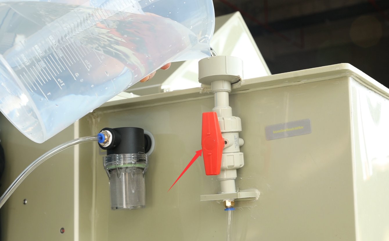
После добавления воды вручную обязательно закройте клапан; в противном случае во время проверки вода будет разбрызгиваться под высоким давлением.
If water is not added manually, the system will automatically replenish water from the purified water tank when the saturation tank runs low after the unit is turned on or during testing.
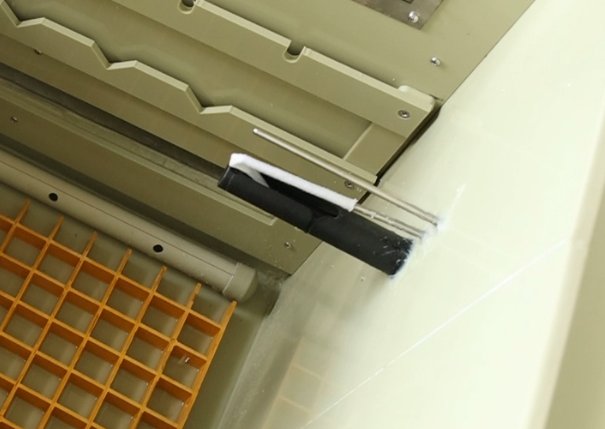
3.3.2 Filling the Gauze Trough Water Tank
Add an adequate amount of pure water. This is used to moisten the gauze on the humidity probe and requires very little water. During long-term continuous testing, it is generally not necessary to refill the water. If the water level is low, the program will sound an alarm.
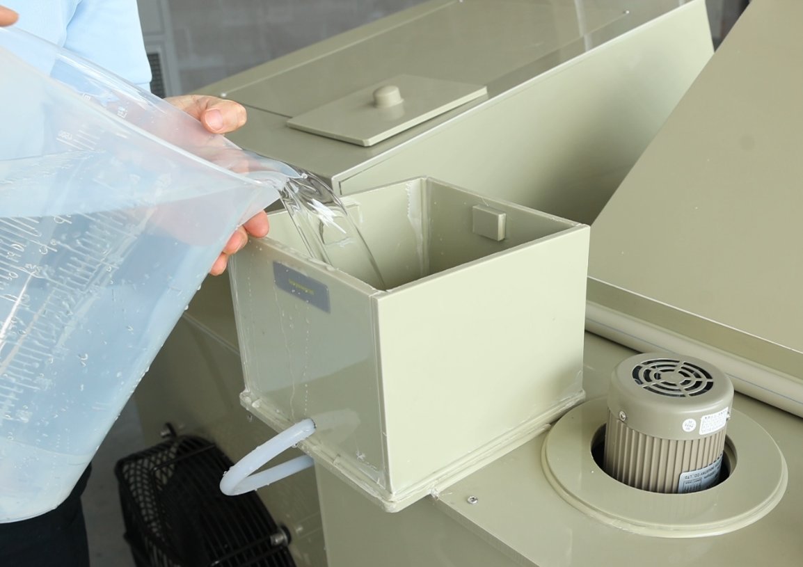
After adding water, it will automatically flow into the gauze reservoir of the humidity probe inside the test chamber. One end of the gauze—at least 50 mm long—should be slipped over the humidity probe, while the other end should be submerged in the reservoir. Ensure that the entire length of the gauze is thoroughly moistened.
3.3.3 Наполнение уплотнительного желоба водой
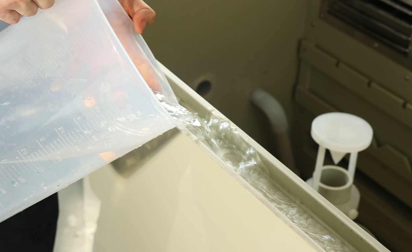
A sealing water trough is installed around the perimeter of the test chamber lid. Fill the trough with clean water until the water level is 2–3 cm above the bottom of the trough to ensure that the test chamber remains airtight after the lid is closed, preventing salt spray from leaking through gaps in the lid during the test.
3.4 Приготовление и введение физиологического раствора
3.4.1 Selection and Preparation of Saltwater Concentration
В соответствии с требованиями стандарта испытаний выберите соответствующий тип солевого тумана и приготовьте раствор. Наиболее распространенные типы следующие:
|
Виды солевого тумана |
Применимые стандарты |
Метод приготовления |
Важные замечания |
|
Нейтральный солевой туман (НСО) |
ГБ/Т 10125, ИСО 9227 |
500 g analytically pure sodium chloride + 9500 mL purified water; stir until the sodium chloride is completely dissolved, resulting in a 5% solution |
Sodium chloride must be completely dissolved, with no precipitate; purified water must meet the Grade 1 standards specified in GB/T 6682. |
|
Кислотно-солевой туман (AASS) |
ГБ/Т 10125, ИСО 9227 |
Медленно добавляйте ледяную уксусную кислоту в раствор NSS и используйте pH-метр (или индикаторную бумагу с точностью до 0.1) для регулирования pH до 3.0–3.1. |
Glacial acetic acid is corrosive; wear gloves and safety goggles, and add it slowly in drops to avoid splashing. |
|
Медьсодержащий солевой туман (CASS) |
ГБ/Т 10125, ИСО 9227 |
Добавьте 0.26 г/л безводного хлорида меди(II) к раствору NSS; перемешивайте до полного растворения, затем нагрейте примерно до 50°C для удаления диоксида углерода из раствора; после охлаждения отрегулируйте pH до 3.0–3.1. |
Хлорид меди необходимо точно взвешивать; при нагревании следует соблюдать осторожность, чтобы раствор не выкипел. |
3.4.2 Введение рассола
Open the fill port on the brine tank and slowly pour the prepared brine into the tank, taking care to prevent the solution from splashing and corroding the equipment surface.
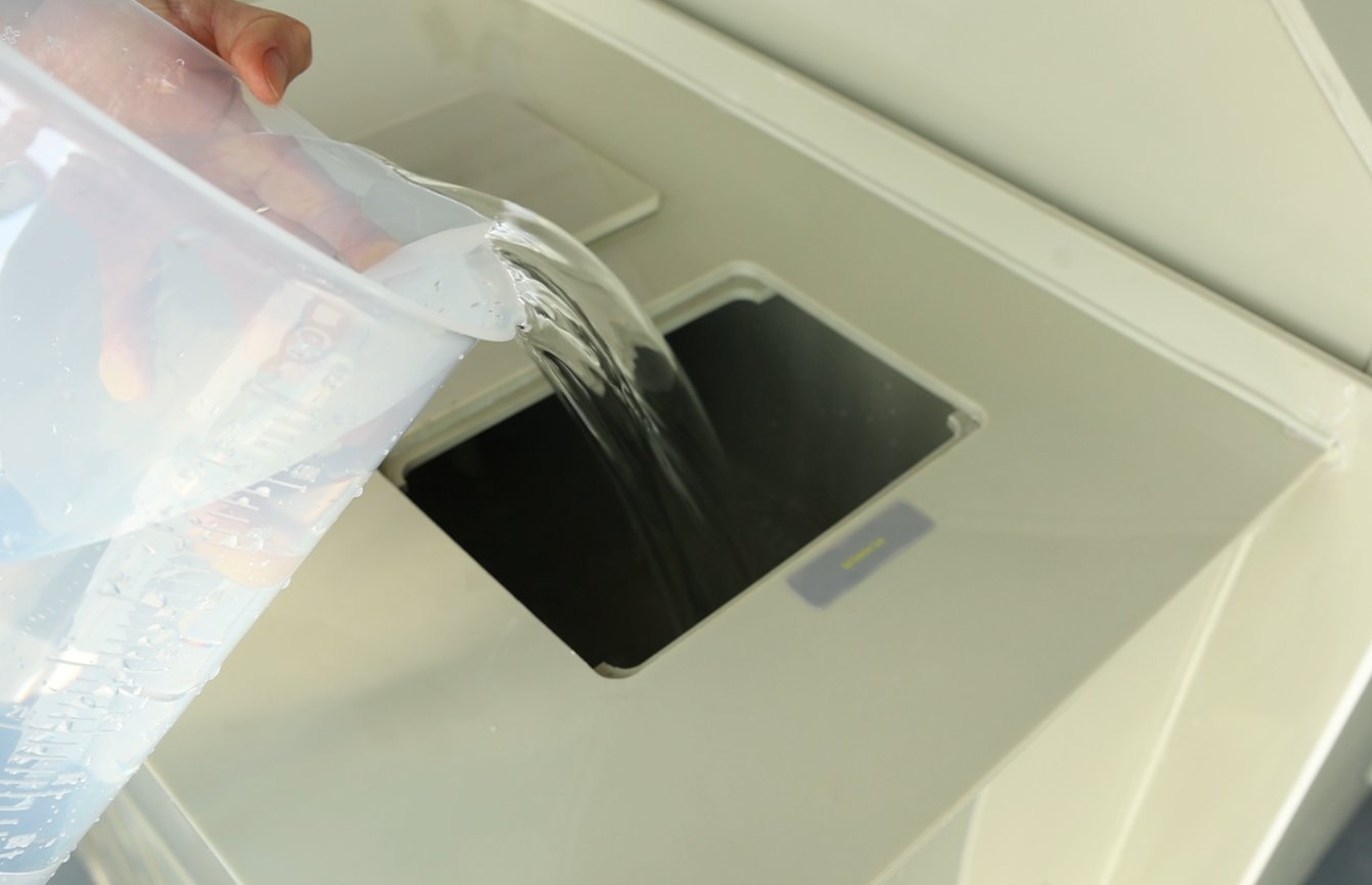
Observe the touchscreen; when the low-salt-water indicator on the salt water tank disappears, it means the salt water has reached the minimum operating level. However, if a long-term test is required (e.g., exceeding 24 hours), you may continue to fill the salt water tank until it is full (without exceeding the overflow port) to reduce the number of times you need to refill the salt water during the test. Approximately 12 liters of brine is sufficient to power one spray tower for 24 hours of continuous spraying.
3.5 Подготовка и загрузка образцов
3.5.1 Очистка образцов
Before testing, clean the sample surface to remove contaminants such as oil, dust, and fingerprints: Gently wipe the surface with a lint-free cotton swab dipped in anhydrous ethanol, or rinse with purified water and allow it to air dry. Avoid excessive wiping, which could damage the sample’s surface coating (such as electroplated or painted layers).
If there is any temporary protective coating on the sample surface (such as a protective film or rust-preventive paper), it must be completely removed to ensure that the sample surface comes into full contact with the salt spray.
3.5.2 Защита кромок
If the sample has cut edges, drilled holes, or marked areas (non-test areas), they must be sealed with heat-resistant, salt-spray-resistant paint or tape to prevent galvanic corrosion in these areas, which could affect the accuracy of the test results.
Необходимо заранее убедиться, что герметизирующий материал не вступает в реакцию с раствором солевого тумана и не загрязнит зону испытания образца.
3.5.3 Выбор держателя и размещение образца
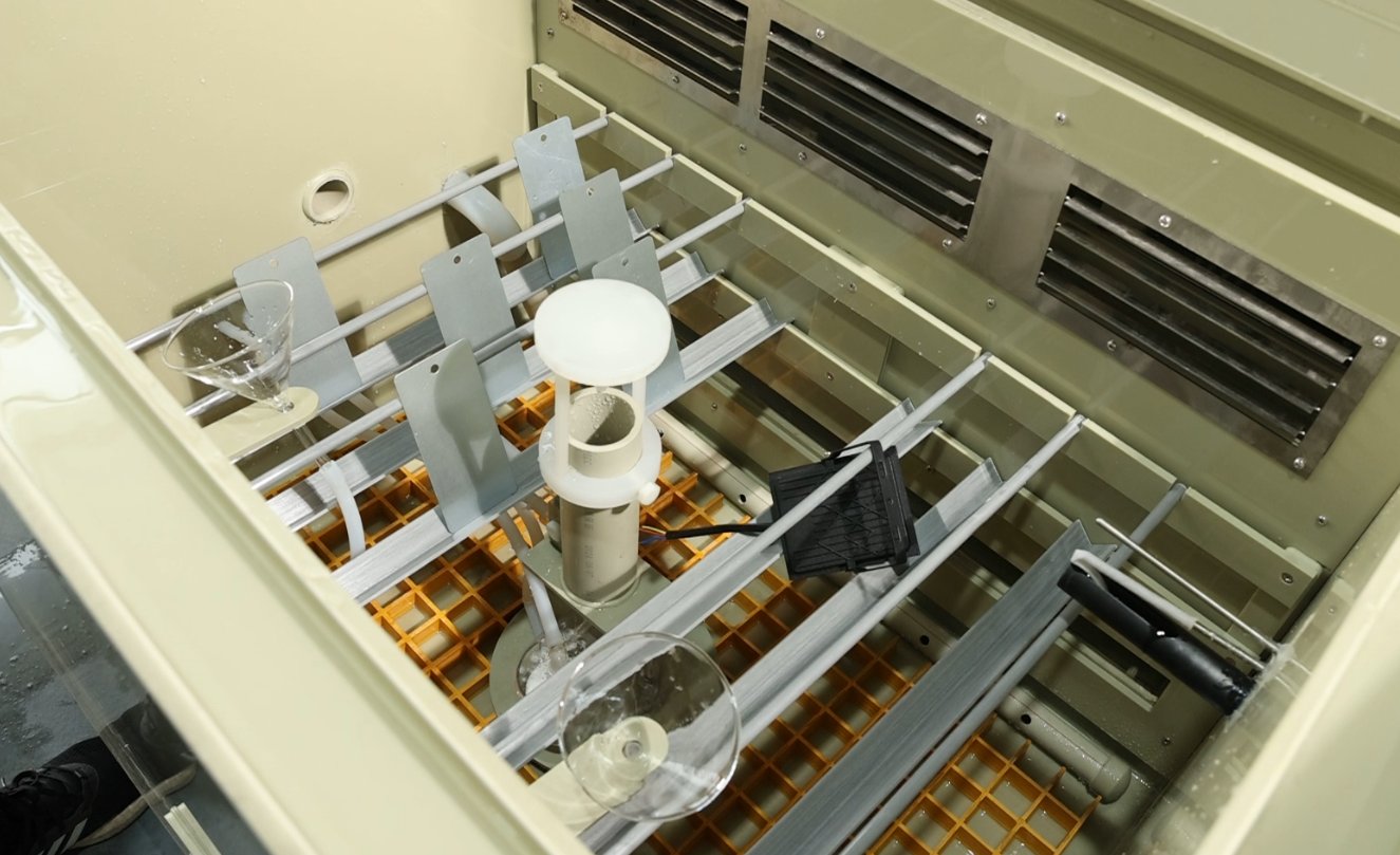
Choosing a Holder: Select a holder based on the sample’s size and shape—small samples can be suspended using round or triangular holders, while large or flat samples can be placed directly on the yellow mesh divider at the bottom of the mist chamber.
Требования к отображению:
Стандартные металлические пластинчатые образцы необходимо размещать под углом 15–25° (угол можно регулировать с помощью штатива) таким образом, чтобы испытательная поверхность образца была параллельна направлению потока солевого тумана, обеспечивая равномерное покрытие солевым туманом;
Sufficient spacing must be maintained between samples (at least 1.5 times the largest dimension of the sample) to prevent the samples from coming into contact with one another or obstructing the salt spray, and salt spray condensation from one sample must not drip onto another sample;
The total volume of the sample must not exceed 3/5 of the chamber volume to avoid disrupting air circulation within the chamber, which could result in uneven temperature and salt spray distribution.
За исключением перегородок и держателей образцов, образцы не контактируют ни с какими другими компонентами внутри испытательной камеры.
3.6 Регулировка давления распыления
For instructions on using the touchscreen, please refer to Chapter 4.
Close the test chamber lid. Go to the “Operation Settings” screen on the touchscreen, select “FIX” mode, and disable the “Fixed Value Standby” function. Go to the “Monitoring Screen,” select only “Salt Spray” as the operating mode, start the test, and begin spraying immediately.
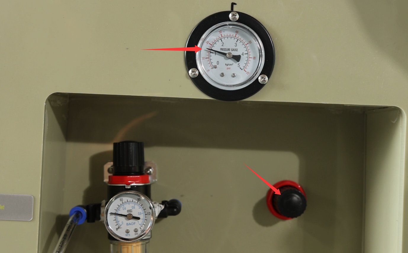
Adjust the pressure regulating valve shown in the figure below so that the spray pressure gauge reads 1 kg/cm² (0.1 MPa). Observe the spray pattern from the nozzles inside the spray chamber: the spray should form a fine, uniform mist with no water droplets or interruptions, and the spray range of the spray tower (if present) should cover the entire spray chamber.
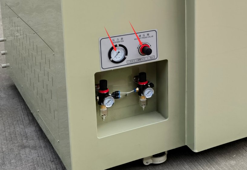
If your test chamber uses a pneumatic cylinder to open the lid, the spray pressure regulator and spray pressure gauge are located as follows:
After pre-spraying for 5 to 10 minutes, verify that the spray is uniform, with no water droplets and no interruptions in the spray pattern.
4. Процедура тестирования (основные операции на сенсорном экране)
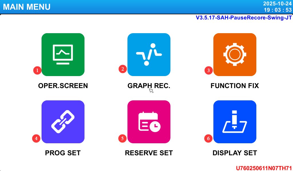
Главное меню с сенсорным экраном:
|
Проект |
Имя |
Внимание |
|
① |
Кадры видеонаблюдения |
Displays real-time operating data, fault information, and more. |
|
② |
Отображение кривой |
View test curves; data backup is supported. |
|
③ |
Настройки работы |
Select test mode (fixed value/program), power-off mode, etc. |
|
④ |
Настройки программы |
Edit a multi-segment test program. |
|
⑤ |
Настройки назначения |
Set the scheduled start time and the current time. |
|
⑥ |
Параметры дисплея |
Change the language, adjust the screen backlight timeout, and more. |
4.1 Введение в экран настроек работы
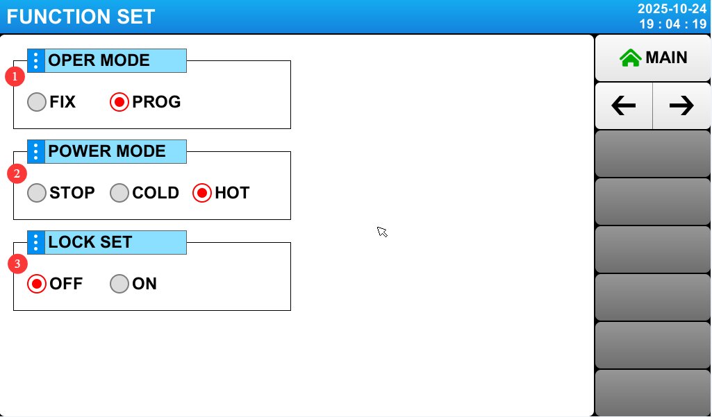
Перейдите на экран «Настройки работы»:
|
Проект |
Имя |
Внимание |
|
① |
Режимы работы |
Select either the FIX test or the PROG test. |
|
② |
Режим отключения питания |
Configure power-up operations in the event of a power outage. ☞ Stop: The operation that restores the system to the “Stop” state when power is restored after a power outage during operation . ☞ Cold Start: The operation that restarts the system when power is restored after a power outage during operation. ☞ Hot Start: The operation that restores the system to its pre-outage state when power is restored after a power outage during operation. |
|
③ |
Замка |
When the lock is set to “On,” none of the PARAMETER settings can be used. |
Go to page 2 of the “Operation Settings” screen:
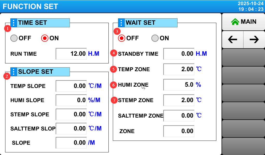
|
Проект |
Имя |
Внимание |
|
① |
Fixed-Value, Fixed-Time Операции |
Set the runtime; this applies only when operating at a fixed value. If set to 0, you’ll need to click “Stop” manually. |
|
② |
Fixed Slope |
Unless otherwise specified, do not modify this setting; simply use the default value of 0, and the device will operate at an automatic slope. Setting any other value may cause the device to malfunction. |
|
③ |
Fixed-Value Wait Настройки |
Standby Function and Standby Parameter Settings. If this function is enabled, the test timer will not start until the device reaches the target value (for salt spray tests, spraying will not begin until the target temperature is reached). ☞ Example: Set the temperature to 60°C, select “On” for Standby, set the temperature range to 1.00, and set the standby time to 1.00. Timing begins when the measured temperature reaches 60±1°C. If the target value is not reached within 1 hour, the test timer will automatically start. |
|
④ |
Время ожидания |
Set the maximum duration for “fixed-value wait.” |
|
⑤ |
Temperature Zones in the Test Chamber |
If the setting is 2—that is, when the actual temperature differs from the target temperature by 2°C—the target temperature is considered to have been reached. |
|
⑥ |
Humidity Zone of the Test Chamber |
If the setting is 5—meaning that when the actual humidity differs from the target humidity by 5%—the target humidity is considered to have been reached. |
|
⑦ |
Saturated Zone Temperature Range |
If the setting is 2—that is, when the actual temperature differs from the target temperature by 2°C—the target temperature is considered to have been reached. |
4.2 Введение в экран настроек записи на прием
Перейдите на экран «Настройки расписания»:
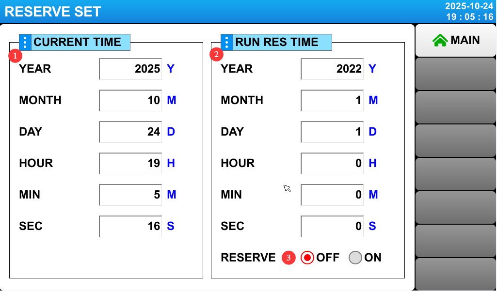
|
Проект |
Имя |
Внимание |
|
① |
Текущее время |
Displays or sets the current time. |
|
② |
Время встречи |
You can set an appointment time. |
|
③ |
Настройки назначения |
If the scheduling setting is enabled, the device will automatically run the selected test at the scheduled time. |
4.3 Introduction to Display Settings
Go to “Display Settings”:
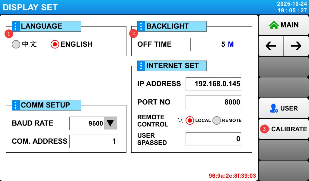
|
Проект |
Имя |
Внимание |
|
① |
Переключатель языка |
You can switch the display language between Chinese and English. |
|
② |
Продолжительность подсветки |
You can set the touchscreen backlight timeout. |
|
③ |
Сенсорная калибровка |
If the touchscreen is not responding accurately, enter Calibration mode. Contact LISUN Служба поддержки клиентов за помощью. |
4.4 Калибровочный тест (FIX)
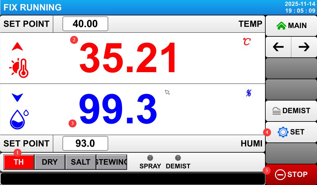
4.4.1 Введение в экран проверки калибровки
Go to the “Operation Settings” screen, select “FIX” for “Operation Mode,” and then go to the “Monitoring Screen.”
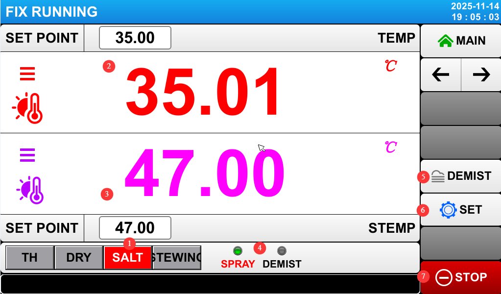
|
Проект |
Имя |
Внимание |
|
① |
Selecting a Salt Spray Test |
In the salt spray test interface, temperature, humidity, and drying tests cannot be performed. |
|
② |
Temperature of the Test Chamber (Fog Chamber) |
Displays the current test chamber temperature; you can set the desired test chamber temperature. The default setting is 35°C (the standard temperature for NSS/AASS testing). If you need a different temperature, you can enter it using the touchpad (the range is typically 10–60°C). |
|
③ |
Температура насыщенного барабана |
Displays the current saturation temperature; you can set the desired saturation temperature value. The default setting is 47°C (to ensure saturated air humidity and prevent spray cooling), which should be 10–15°C higher than the test chamber temperature. |
|
④ |
Spray and Demist Modes |
Отображает текущий статус распыления и противотуманной обработки. |
|
⑤ |
Manual Defogging |
Press this button to activate the defogging function; compressed air will enter the test chamber to quickly remove fog. |
|
⑥ |
Fixed-Value Test Settings |
Click to open the fixed-value test settings screen. |
|
⑦ |
Кнопка Run |
Click to start or stop the current test. |
|
Проект |
Имя |
Внимание |
|
① |
Select Temperature and Humidity Testing |
Salt spray and drying tests cannot be performed in the temperature and humidity test interface. |
|
② |
Температура испытательной камеры |
Displays the current temperature of the test chamber; you can set the desired temperature for the test chamber. |
|
③ |
Влажность в испытательной камере |
Displays the current humidity level in the test chamber; you can set the desired humidity level for the test chamber. |
|
④ |
Fixed-Value Test Settings |
Click to open the fixed-value test settings screen. |
|
⑤ |
Кнопка запуска |
Click to start or stop the current test. |
|
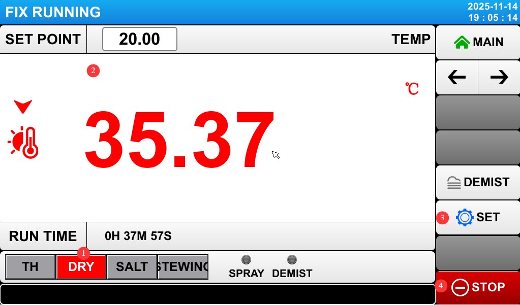
Проекты |
Имя |
Внимание |
|
① |
Select Drying Test |
In the drying test interface, salt spray and temperature/humidity tests cannot be performed. |
|
② |
Температура испытательной камеры |
Displays the current temperature of the test chamber; you can set the desired temperature for the test chamber. |
|
③ |
Fixed-Value Test Settings |
Click to open the fixed-value test settings screen. |
|
⑤ |
Кнопка Run |
Click to start or stop the current test. |
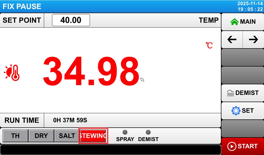
If you select the “static” test, the test chamber will remain completely still; once the test begins, the samples remain stationary inside the test chamber.
4.4.2 Introduction to the Fixed-Value Test Settings Screen
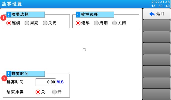
On the “Monitoring Screen” of the calibration test, click “Settings” to open the parameter settings screen:
|
Проект |
Имя |
Внимание |
|
① |
Варианты распыления |
Continuous, Cyclic, Off. |
|
② |
Defogging Time |
Enable the “End Defogging” function and enter the defogging time; the system will then automatically perform defogging once the salt spray test is complete. If the “End Defogging” function is enabled, manual defogging is no longer required. |
4.5 Program Testing (Multi-Mode Automatic Switching)
Go to the “Operation Settings” screen, select “Program (PROG)” under “Operation Mode,” and then go to the “Program Settings” screen:
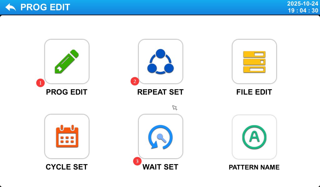
|
Проект |
Имя |
Внимание |
|
① |
Редактирование программы |
Edit the program number, name, test segment number, and other parameters. |
|
② |
Настройки петли |
Loop testing mode for editing programs. |
|
③ |
Настройки режима ожидания |
Wait Function and Wait Parameter Settings. |
4.5.1 Введение в экран редактора программ
Go to the “Program Editor” screen:
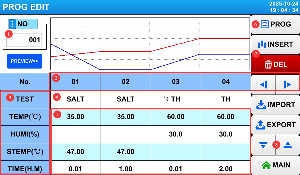
|
Проект |
Имя |
Внимание |
|
① |
Номер программы |
Enter the program number; up to 120 programs are supported. Be sure to avoid duplicating existing program numbers. |
|
② |
Test Segment Number |
Click the left and right arrow buttons on the right to switch to other test sections. |
|
③ |
Тестовые задания |
From top to bottom, in order: test mode, test chamber temperature, test chamber humidity, saturated bucket temperature, and test duration. |
|
④ |
Тестовый режим |
Click to set the mode for the corresponding test section: Temperature and Humidity (TH), Salt Spray (SALT), Dry (DRY), or Stewing (STEWING). |
|
⑤ |
Настройки параметров теста |
For temperature and humidity (TH), set the chamber temperature and humidity; for salt spray (SALT), set the chamber temperature and the saturated bucket temperature; for drying (DRY), set the chamber temperature; For the Stewing (STEWING) test, none of these parameters need to be set . Test Duration Settings: With the same temperature and humidity settings, you must configure two consecutive test segments. The first segment is a transition phase and should be set to 1 minute (the actual duration may exceed 1 minute; the test chamber has a wait function that will reach the set temperature as quickly as possible and then automatically advance to the next segment). The second segment is the actual test duration. |
|
⑥ |
Click to return to the program settings screen. |
|
|
⑦ |
Click to insert or delete a test section. |
|
|
⑧ |
Press the up and down arrow keys to access the settings for other test items. |
Press the “Down” arrow key to access the “Spray” and “Defrost” settings screen:
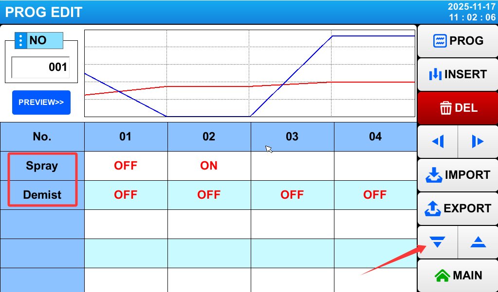
The spray function does not need to be enabled during the transition phase, temperature and humidity testing, drying testing, or static testing; simply set it to OFF. The spray function must be enabled—that is, set to ON—only during the actual salt spray test phase.
A defogging test segment can be added at an appropriate point, such as after each salt spray test segment. Set the test mode to “Stewing” and set the “Defogging” function to ON. Set the duration of the defogging test segment to 5 minutes.
4.5.2 Introduction to the Loop Settings Screen
Перейдите на экран «Настройки цикла»:

|
Проект |
Имя |
Внимание |
|
① |
Выбор программы |
Select the currently set program number. |
|
② |
Количество циклов |
Indicate whether the current program should perform a loop. If a loop is not needed, simply enter 1—this means the program will run once. |
|
③ |
Ссылки на программу |
If you want this program to automatically connect to another program for testing after it finishes running, enter the corresponding program number; if not, simply enter 0. |
|
④ |
Частичный цикл |
Loop sequence settings: If you want to test segments 1 through 2 of this program twice and segments 3 through 4 three times, set the three fields in the first column to 1, 2, and 2, respectively.and set the three windows in the second column to 3, 4, and 3, respectively. This means that the sequence of segments throughout the entire test program will be 1, 2, 1, 2, 3, 4, 3, 4, 3, 4, 5…, and so on. If this function is not needed, simply set all windows to 0. |
|
⑤ |
Click to return to the program settings screen. |
4.5.3 Introduction to the Standby Settings Screen
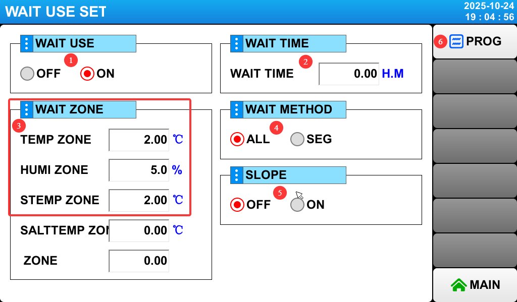
Wait Function and Wait Parameter Settings. If this function is enabled, the test timer will not start until the device reaches the target value (for salt spray tests, spraying will not begin until the test reaches the target temperature).
Go to the “Standby Settings” screen:
|
Проект |
Имя |
Внимание |
|
① |
Wait Function |
Please set this to ON to enable the standby feature. |
|
② |
Время ожидания |
Set the maximum wait time. |
|
③ |
Waiting Range |
From top to bottom, in order: test chamber temperature, test chamber humidity, and saturated bucket temperature. |
|
④ |
Ожидание конфигурации |
Just select “All,” and the wait function will be enabled for all test segments. |
|
⑤ |
Режим наклона |
Unless otherwise specified, please do not modify this setting; simply use the default value of 0, and the device will operate at the automatic slope. Setting any other value may cause the device to malfunction. |
|
⑥ |
Click to return to the program settings screen. |
4.5.4 Running the Program Test
Return to the “Monitoring Screen”:
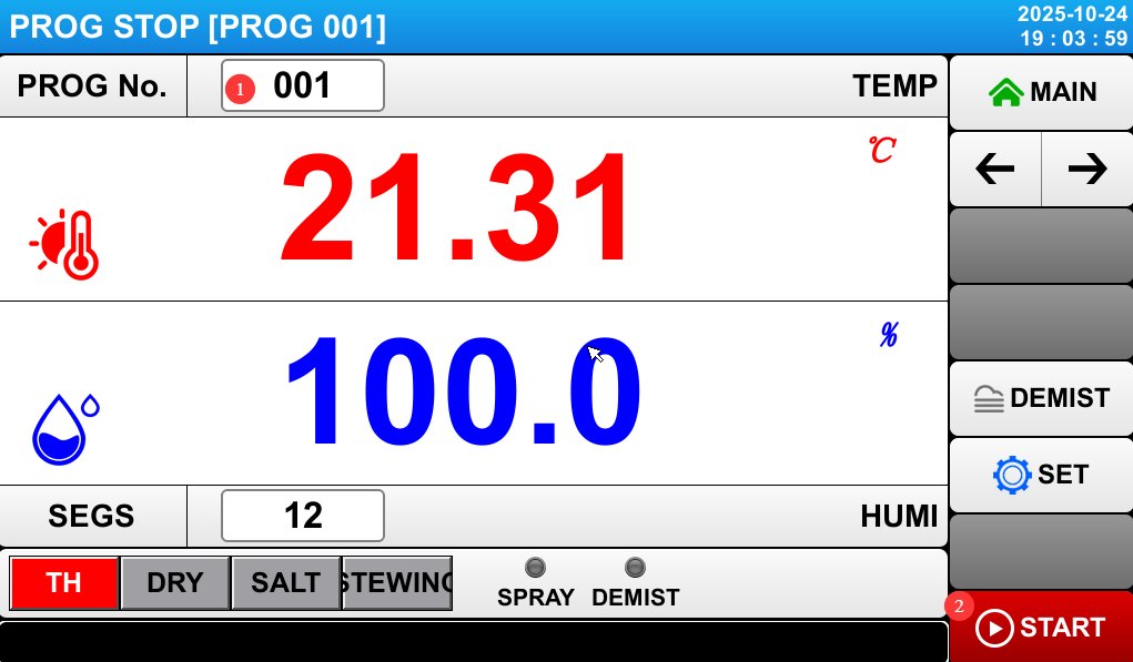
|
Проект |
Имя |
Внимание |
|
① |
Выбор программы |
Enter the program number you want to run. |
|
② |
Run |
Click to start or stop the process. |
4.6 Мониторинг процесса тестирования
4.6.1 Мониторинг температуры и влажности
Monitor the temperature of the test chamber, the humidity inside the test chamber, and the temperature of the saturation chamber displayed on the touchscreen in real time. For temperature and humidity testing, the test chamber temperature will rise slowly to the target temperature, followed by the humidity slowly reaching the target level, after which the system will stabilize; For salt spray testing, both the chamber temperature and the saturated bucket temperature will gradually reach their target values simultaneously and then stabilize; for dry testing, the chamber temperature will gradually reach its target value and then stabilize. If temperature or humidity readings are abnormal, stop the test and refer to Chapter 6 for troubleshooting.
4.6.2 Мониторинг уровня воды
Pure Water Tank: Keep the water supply valve open at all times; the tank will automatically replenish the humidification chamber and the saturation tank. Humidification Chamber: Used for humidity testing, located inside the test chamber; no inspection is required. It is automatically replenished from the pure water tank without the need for manual intervention. Saturation Tank: If the water level drops to the alarm threshold, the system will automatically refill from the purified water tank. During refilling, the test will automatically pause temporarily and resume automatically once refilling is complete, requiring no manual intervention;
Brine Tank: The brine in the brine tank is used for spray testing and will be consumed; please refill it as described in Section 3.4.2. Gauze Tray Water Tank: The water in this tank is not consumed, and if the equipment is placed on a level surface, the water will not leak out, so refilling is generally not necessary.
4.6.3 Контроль распыления
Observe the spray pattern through the glass door of the mist chamber to ensure that the spray is uniform and uninterrupted. If any abnormalities are detected (such as a decrease in spray volume or water dripping from the nozzle), pause the test to check whether the nozzle is clogged or whether the air pressure is stable.
4.6.4 Запись данных
Record the test duration, laboratory temperature, laboratory humidity, saturated bucket temperature, brine level, and spray status every 2 to 4 hours; you can also export all historical data after the test is complete.
4.7 End of Test and Shutdown
4.7.1 Spray Shut-off and Defogging
Timed End: If a test duration has been set, the device will automatically stop spraying when the time elapses and enter the defogging mode (if the “End Defogging” function is enabled). Once defogging is complete, the touchscreen will display “Test Complete.”
Manual Stop: If you need to stop the test early, tap the “Stop” button on the touchscreen. The equipment will stop spraying, and you can choose whether to activate the defogging function (tap the “Manual Defogging” button). Once the salt fog has been expelled from the fog chamber, turn off the “Manual Defogging” button before proceeding with subsequent operations.
If a defogging test segment is configured in the program test, manual defogging is not required after the program test is complete.
4.7.2 Организация данных и поиск образцов
Data Organization: Record the total test duration, actual temperature curves, and any anomalies (such as mid-test water replenishment or alarms); export and save historical data; and organize the test record forms.
Removing the Sample: After the defogging process is complete, let the sample stand for 5 minutes. Wear acid- and alkali-resistant gloves, open the chamber door, and carefully remove the sample (taking care to prevent salt deposits from falling off the sample’s surface). Place the sample on a clean tray and label it with the relevant information (such as the test number and test duration).
4.7.3 Отключение оборудования
Выключите воздушный компрессор или отсоедините воздухозаборный шланг и отключите питание испытательной камеры.
5. Посттестовая обработка
5.1 Подготовка проб
5.1.1 Очистка и сушка образцов
Очистка: В соответствии с требованиями стандарта испытаний, аккуратно промойте поверхность образца очищенной водой (или дистиллированной водой) при температуре ≤38°C для удаления остаточных солевых отложений. Избегайте интенсивного промывания, которое может повредить продукты коррозии образца (такие как слои ржавчины или окисления); если это разрешено стандартом, для удаления стойких солевых отложений можно нанести небольшое количество нейтрального моющего средства (например, средства для мытья посуды), после чего тщательно промыть очищенной водой.
Сушка: После промывки промокните поверхность образца чистой обезжиренной ватой или фильтровальной бумагой, или поместите образец в вентилируемый сушильный шкаф при комнатной температуре (без нагрева) для просушки на воздухе. Избегайте прямых солнечных лучей или сушки при высоких температурах, чтобы предотвратить изменение состояния поверхности образца.
5.1.2 Оценка образца
Визуальный осмотр: Осмотрите поверхность образца на наличие признаков ржавчины, изменения цвета, отслоения покрытия, образования пузырей и т. д. Зафиксируйте площадь, пораженную коррозией, и степень ее тяжести (например, слабая, умеренная, сильная). Сделайте фотографии для последующего сравнения.
Performance Testing: Depending on the purpose of the test, conduct follow-up performance tests on the samples (such as adhesion testing, impact resistance testing, and electrical performance testing) to evaluate the impact of salt spray corrosion on the samples’ performance, and compile an evaluation report.
5.2 Очистка оборудования
5.2.1 Очистка туманной камеры
Промойте внутренние стенки камеры распыления, распылительной башни, туманосборника и сетчатых перегородок очищенной водой, чтобы удалить остатки солевых отложений и накипи. Для удаления стойких пятен аккуратно потрите мягкой щеткой, смоченной в нейтральном моющем средстве, затем тщательно промойте очищенной водой.
Cleaning the Temperature Probe: Wipe the temperature probe with a soft cloth to remove any salt spray that has accumulated on it.
Cleaning the Humidity Sensor Gauze: If the gauze is soiled, remove it, clean it, and then reinsert it. If the gauze loses its ability to absorb moisture, it may cause abnormal humidity readings. Generally, replace the gauze every three months (use 100% cotton or medical-grade non-woven gauze).
5.2.2 Очистка резервуара насыщения
Before cleaning, first close the automatic refill valve on the purified water tank, then drain the water from the tank. Open the drain valve on the saturation tank (located at the bottom of the test chamber), drain out any remaining water, close the drain valve, and then fill the tank with a 5% citric acid solution. Let it soak for 20–30 minutes (to remove scale from the inner walls of the tank), then drain the solution and rinse the tank 2–3 times with purified water to ensure no citric acid residue remains.
Cleaning the saturated tank liquid level sensor: Wipe the sensor probe with a soft cloth dipped in purified water to remove scale and ensure accurate liquid level detection.
5.2.3 Очистка резервуара с рассолом и форсунок
Brine Tank: Rinse the inner walls of the tank with purified water to remove any residual brine and sediment. If there are salt crystals, soak the tank in warm water, then scrub them off. After rinsing thoroughly, let the tank air dry.
Nozzle Cleaning: Remove the nozzle and gently clear the small holes in the nozzle with a fine copper wire (diameter ≤ 0.5 mm), taking care not to apply excessive force that could damage the nozzle; Soak the nozzle in a 5% citric acid solution for 15 minutes to remove scale, then rinse thoroughly with purified water. Allow it to air dry before reinstalling (ensuring the small holes in the glass tube of the nozzle are aligned); If the nozzle is cracked, the orifice is deformed, or it fails to spray properly even after cleaning, replace it with a spare nozzle.
5.2.4 система охлаждения
Use an air gun to remove dust and debris from the condenser fins, as shown in the figure below:
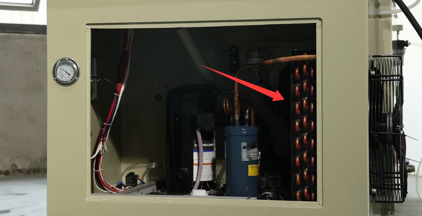
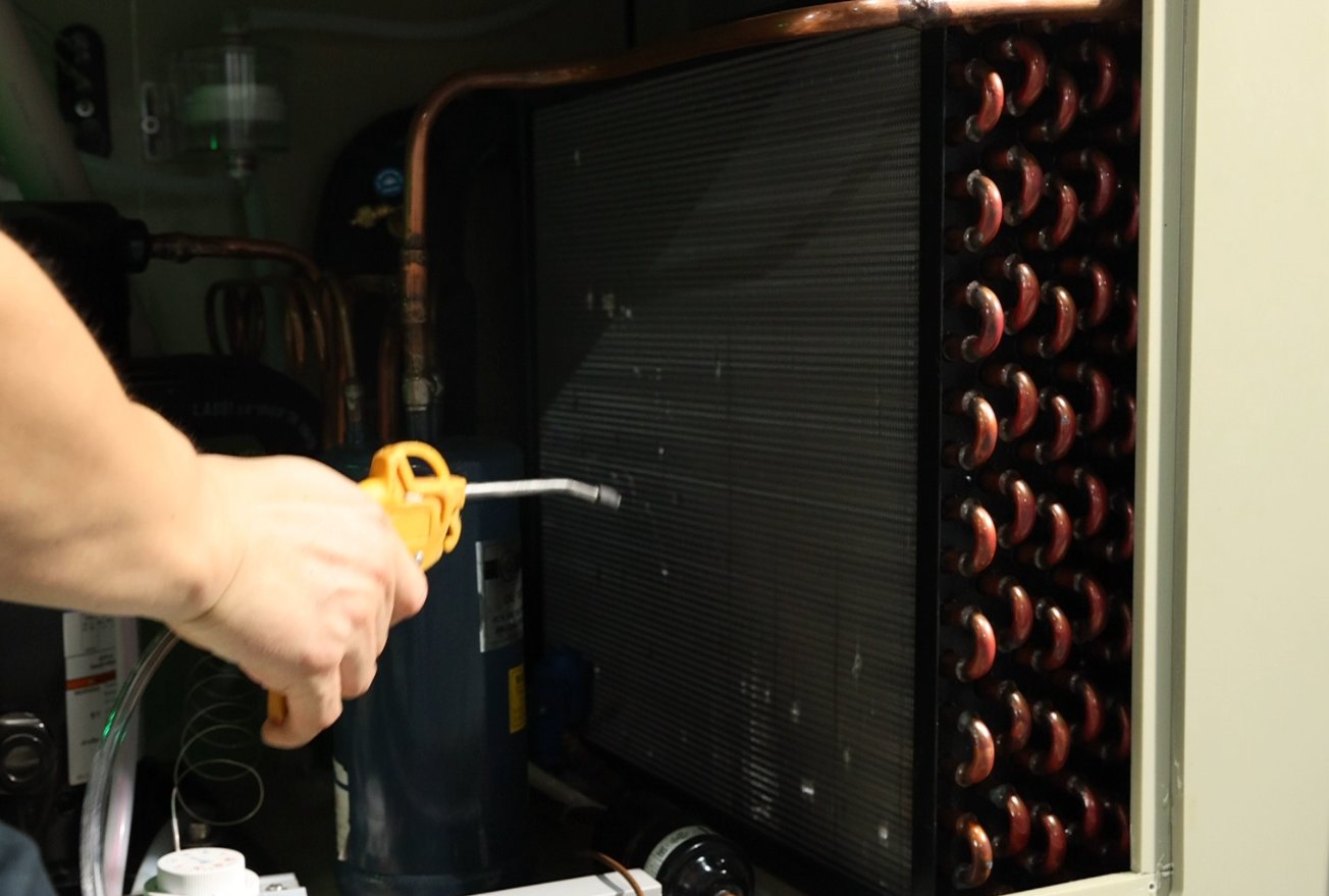
Check the refrigerant pressure (≥12 kg during operation) and top it off promptly if it is low.
5.3 Требования к долговременному хранению
5.3.1 Подготовка перед хранением
Если оборудование не будет использоваться в течение длительного периода (более 1 месяца), выполните следующие действия:
Shut off water, electricity, and air: Disable the automatic refill function of the purified water tank; disconnect the equipment from the power source; disconnect the air hose from the air compressor; and turn off the air compressor’s power;
Thoroughly clean the equipment: Clean the fog chamber, saturation tank, brine tank, and nozzles according to the steps in “5.2 Equipment Cleaning” to ensure no salt residue remains;
Drain all liquids: Open all drain valves to remove any residual water from the components, and use compressed air to dry the interior (to prevent moisture and rust);
Защита компонентов: Накройте оборудование пылезащитным чехлом, чтобы предотвратить попадание пыли.
5.3.2 Техническое обслуживание во время хранения
Условия хранения должны соответствовать требованиям, указанным в разделе 2.3.1;
Power on once a month: Turn on the power to the equipment and let it run for 30 minutes (no need to add water or brine) to prevent electrical components (such as capacitors and contactors) from deteriorating;
Проводите осмотр раз в месяц: откройте пылезащитный кожух и проверьте внутреннюю часть оборудования на наличие ржавчины или плесени; при обнаружении немедленно очистите и высушите его. Проверьте шланги на наличие признаков износа и убедитесь в надежности соединений.
6. Устранение распространенных проблем
If the device malfunctions, please refer to the following common issues and troubleshooting steps:
|
Общие проблемы |
Возможные причины |
Метод |
|
Туманная камера / Резервуар насыщения не нагреваются |
1. Недостаточный уровень жидкости; 2. Сгоревший нагревательный элемент; 3. Неисправный регулятор температуры; 4. Поврежденный датчик температуры. |
1. Top off the fluid until the alarm clears; 2. Disconnect the power supply and check the resistance of the heating element (normally several tens of ohms); if it is burned out, replace it; 3. Restart the equipment; if there is still no response, contact customer service to have the controller repaired; 4. Check the probe wiring; if damaged, replace it. |
|
Без спрея |
1. Недостаток рассола; 2. Засорение форсунки; 3. Утечка воздуха (например, отсоединенный воздушный шланг, поврежденный электромагнитный клапан); 4. Неправильная регулировка давления воздуха. |
1. Refill with saline solution; 2. Clean the nozzle (see 5.2.3); 3. Check the air tube connections and replace any damaged solenoid valves; 4. Readjust the air pressure (0.2 MPa at the back, 1 kg/cm² at the front) |
|
The temperature cannot reach the setpoint |
1. Недостаточная мощность нагревательного элемента; 2. Неисправность датчика уровня жидкости (некорректное отображение уровня жидкости); 3. Слишком низкая температура окружающей среды; 4. Плохое уплотнение дверцы. |
1. Check the heating element’s wattage and replace it with a compatible one; 2. Clean or replace the liquid level sensor; 3. Adjust the ambient temperature (e.g., turn up the heat); 4. Check the water level in the sealing tank and top it off to the standard level. |
|
Передний манометр не может быть отрегулирован на более высокое значение. |
1. Ручной клапан заправки водой на расширительном баке не закрыт; 2. Воздушный шланг форсунки ослаб или треснул; 3. Электромагнитный клапан распылителя поврежден. |
1. Закройте ручной клапан подачи воды; 2. Замените или подсоедините воздушный шланг; 3. Установите на место электромагнитный клапан. |
|
Humidity Display Error |
Humidity sensor gauze malfunction; 2. Humidifier water tank malfunction |
Clean or replace the gauze; 2. Remove the rear panel from the inner compartment and check the condition of the humidifier water tray. |