
 Английский
 中文简体
中文简体 Русский
 Español
 Português
 Türkçe
 العربية
 Deutsch
 Polski
 Italiano
 Français
 한국어
한국어 ไทย
ไทย Tiếng Việt
 日本語
日本語





























Тестер повышения температуры
Руководство пользователя
Применимый LISUN models: WS-8-200A、WS-8-300A、WS-8-50A
1. Базовое понимание оборудования
1.1 Ключевые технические характеристики
| Номер регистрации | WS-8-50A | WS-8-200A | WС-8-300А |
|---|---|---|---|
| Испытательная станция | 8 | ||
| Тестовый ток | 0-50 A | 0-200 A | 0-300 A |
| Испытательное напряжение | Меньше 3V | ||
| Система управления | Equipped with a touchscreen display, it automatically controls the on-off sequencing and fully complies with the test requirements of Clause 19.5.1 of IEC 60884-1: 2022. | ||
| Таймер | Регулируется от 0 до 9999 секунд | ||
| В соответствии со стандартом | GB/T 2099.1, пункт 19 (IEC 60884-1Пункт 19) | GB/T 2099.1, пункт 19 (IEC 60884-1в соответствии с пунктом 19), требованиями GB 16915.1, пунктом 17 (IEC 60669-1, пункт 17) и GB/T 13140.1, пунктом 15 (IEC 60998-1, пункт 15) | |
1.2 Распаковка и проверка содержимого
1.2.1 Распаковка и визуальный осмотр
При распаковке устройства обращайтесь с ним осторожно, чтобы не поцарапать корпус острыми предметами. После распаковки сначала осмотрите внешний вид устройства, чтобы убедиться в отсутствии видимых деформаций или вмятин, а также в том, что кнопки не повреждены и не расшатаны.
If you find that the equipment or accessories are damaged or deformed, do not turn on the power. Пожалуйста, свяжитесь с нами немедленно.
1.2.2 Основной блок и принадлежности
Прибор для измерения повышения температуры: 1 шт.
See Figure 1-1 for standard accessories.
| Номер регистрации | Внимание |
|---|---|
| ① | Standard Test Model for Flush-Mounted Outlets |
| ② | Шнур питания |
| ③ | Трубопровод |
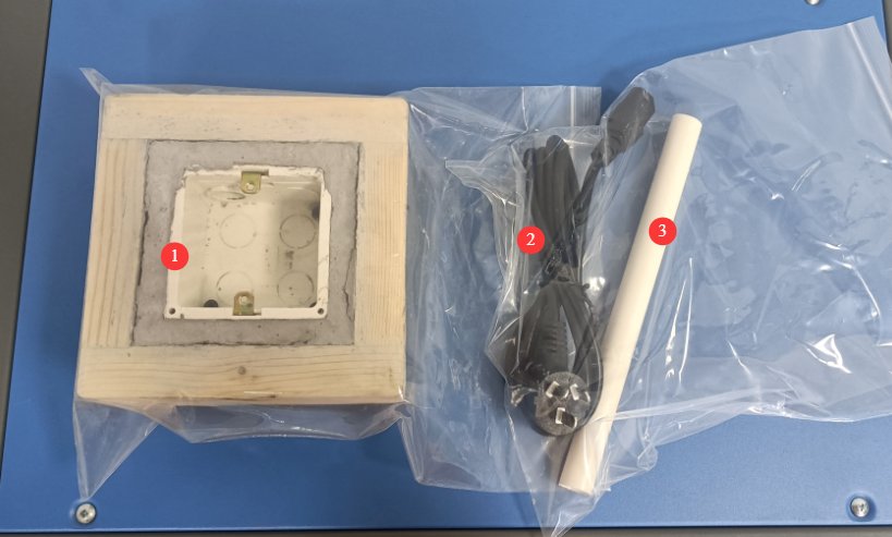
Note: The WS-8 series Temperature Rise Tester provides only high-current load output and does not include temperature acquisition or recording functions; it must be used in conjunction with a TMP series Multiplex Temperature Tester during testing.
2. Меры предосторожности при использовании
2.1 Электрическая безопасность
2.1.1 Подключение питания
AC 220 V, 50/60 Hz, single-phase power. Power outlets must comply with safety standards, provide proper grounding, and have a rated current that matches the equipment’s power rating and the actual load power requirements.
2.1.2 Технические характеристики заземления
The equipment must be properly grounded, with a grounding resistance of ≤4 Ω. Do not use gas lines, non-metallic water pipes, or the neutral wire as a substitute for the grounding wire. After grounding is complete, use a Grounding Resistance Tester to measure the grounding resistance. Power may only be applied after confirming that it meets the requirements to prevent electric shock, equipment malfunctions, or measurement errors caused by poor grounding.
2.2 Эксплуатационная безопасность
Перед подключением проводов, осмотром или техническим обслуживанием оборудования необходимо выключить выключатель питания оборудования и основной источник питания, а также убедиться в отсутствии остаточного напряжения, прежде чем продолжить;
Во избежание поражения электрическим током не следует нажимать на выключатель питания, сенсорный экран или кнопки приборов мокрыми руками;
Не размещайте внутри электрощита посторонние предметы (например, инструменты или бумагу), чтобы предотвратить короткое замыкание или повреждение компонентов из-за пыли или других посторонних предметов;
Не подключайте и не отключайте шнуры питания или сигнальные кабели во время работы оборудования, чтобы предотвратить короткие замыкания, которые могут повредить контроллер или электрические компоненты;
Оборудование способно выдавать высокие токи. При подключении проводов, замене образцов или настройке схемы необходимо сначала отключить питание и установить регулятор тока нагрузки на минимальное значение, чтобы исключить выходную нагрузку и предотвратить поражение электрическим током.
Во время испытаний не прикасайтесь к образцу, клеммам термопары или разъемам выходной нагрузки, чтобы избежать ожогов от высоких температур или поражения электрическим током.
Warning signs must be posted in the test area to prohibit unauthorized personnel from approaching and to prevent accidental contact with high-temperature samples or live electrical components.
2.3 Экологическая безопасность
Оборудование необходимо размещать на ровной, сухой и хорошо проветриваемой поверхности в помещении, вдали от легковоспламеняющихся и взрывоопасных материалов, коррозионных газов и сильных магнитных полей.
Оборудование необходимо установить в комната с кондиционеромпри условии поддержания температуры окружающей среды в диапазоне от 5°C до 35°C и относительной влажности ≤ 85%.
The distance between the equipment and walls, as well as surrounding structures (such as other testing equipment and shelving), must be at least 1000 mm to facilitate operation and maintenance; не менее 2000 мм space must be left in front of the equipment to ensure smooth operation, with no obstructions in the surrounding area;
3. Обзор оборудования
3.1 Структура оборудования
3.1.1 Передняя панель устройства
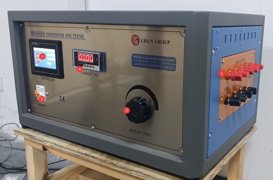
См. Рисунок 3-1.
| Номер регистрации | Внимание |
|---|---|
| ① | Sample connection terminals; up to 8 samples can be connected in series at the same time |
| ② | Выключатель |
| ③ | Test Current Adjustment Knob |
| ④ | Test Current Display |
| ⑤ | сенсорный экран |
3.1.2 Задняя панель устройства
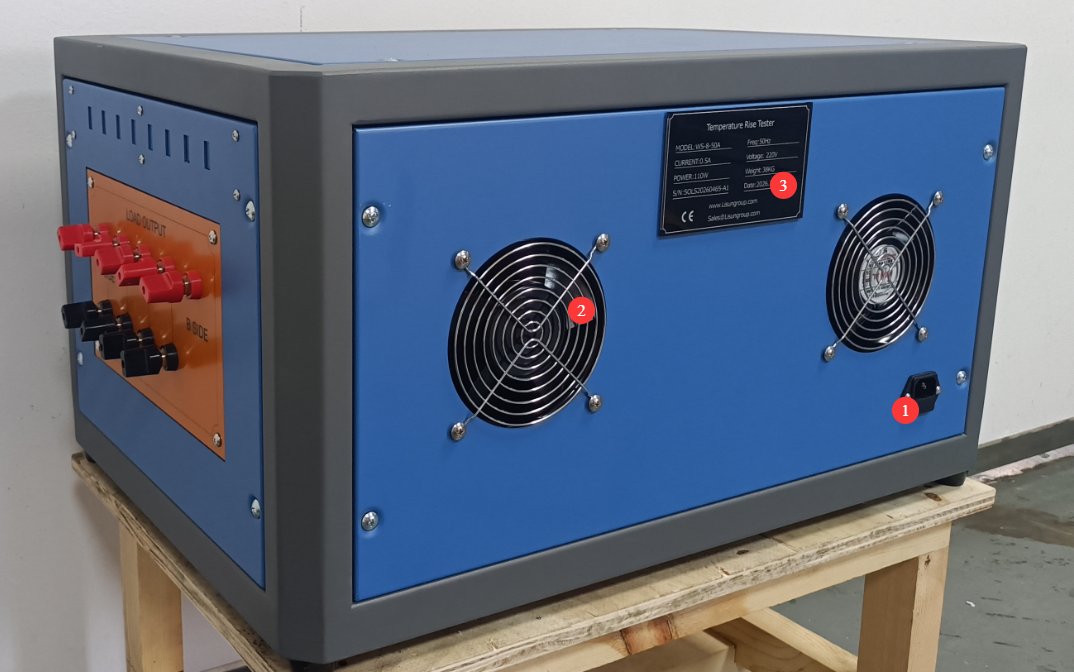
См. Рисунок 3-2.
| Номер регистрации | Внимание |
|---|---|
| ① | Разъем шнура питания |
| ② | Вентилятор |
| ③ | Паспортная табличка продукта |
3.2 Touchscreen Program
3.2.1 Интерфейс тестирования
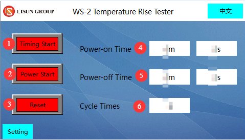
См. Рисунок 3-3.
| Номер регистрации | Внимание |
|---|---|
| ① | Таймер запуска |
| ② | Test Power-On |
| ③ | Сброс |
| ④ | Sample Power-On Duration Display |
| ⑤ | Display of Sample Power-Off Duration |
| ⑥ | Repetition Count Display |
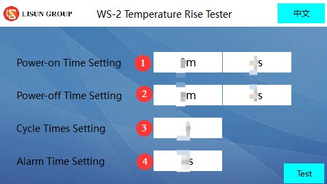
3.2.2 Страница настроек параметров
См. рисунки 3–4.
| Номер регистрации | Внимание |
|---|---|
| ① | Sample Power-On Duration Setting |
| ② | Sample Power-Off Duration Setting |
| ③ | Repetition Count Setting |
| ④ | Alarm Duration Settings |
4. Подготовка к тесту
4.1 Подготовка среды
В соответствии со стандартными требованиями, во время испытаний испытательный стенд следует размещать в защищенном от сквозняков месте, чтобы предотвратить влияние воздушных потоков на точность измерений температуры.
When testing flush-mounted electrical accessories, a test environment that complies with the standards must be set up in advance (see the model in the “General Accessories” section): Place the mounting box into the pine groove and fill the space between the mounting box and the pine groove with plaster, ensuring that the front edge of the mounting box is flush with the front surface of the pine groove (with a deviation not exceeding ±5 mm). The plaster layer should be 10 mm to 15 mm thick, and the pine groove must be surrounded by at least 25 mm of wood on all sides; After the test assembly is constructed, it must be allowed to dry for at least 7 days.
Note: If you need models in other sizes, please contact us or manufacture them yourself according to the standards.
4.2 Confirmation of Standards Used
4.2.1 Определение параметров испытаний
В зависимости от типа исследуемого образца, для определения ключевых параметров обратитесь к соответствующему стандарту:
| Тип образца | Справочные стандарты | Тестовый ток | Продолжительность теста | Предел повышения температуры |
|---|---|---|---|---|
| Розетки/Вилки | GB / T 2099.1-2021 | Как указано в таблице 20 (например, для многорозеточных розеток используйте соответствующий номинальный ток). | 60 ± 5 мин | Клеммы, разъемы и зажимные компоненты ≤ 45 кОм |
| Коммутатор | GB-16915.1 2024 | As specified in Table 17 (e.g., a test current of 20 A for a 16A circuit breaker) | 1h | Клеммы ≤ 45 кОм; неметаллические ручки/кнопки ≤ 5 кОм; другие неметаллические внешние компоненты ≤ 55 кОм; металлические ручки/кнопки ≤ 35 кОм; другие металлические внешние компоненты ≤ 45 кОм |
| Разъемы | GB / T 13140.1-2008 | Как указано в таблице 2 (например, испытательный ток 24 А для пропускной способности соединения сечением 2.5 мм²). | Достижение теплового равновесия (повышение температуры ≤ 1 К в течение 1 часа) | Токонесущие компоненты зажимаемой части ≤ 45 кОм |
| Note: For switches with indicator lights, if the circuit current is ≤3 mA (neon lamp/LED), temperature rise tests related to the indicator light may be omitted; when testing protective devices (such as fuses), use low-impedance wire to short-circuit them. | ||||
4.2.2 Проверка тестового режима
Определите, требуется ли испытание на циклическую нагрузку/холостой ход (см. соответствующие требования стандарта); если испытание на циклическую нагрузку требуется, укажите количество циклов, продолжительность каждого периода включения питания и продолжительность каждого периода выключения питания;
A TMP series Multiplex Temperature Tester is also provided to monitor the sample temperature and ensure that the placement of the thermocouple does not affect measurement accuracy (e.g., near critical areas such as clamping components or terminals).
4.3 Базовые приготовления
4.3.1 Выбор и подготовка образцов
Select representative samples (such as plugs, receptacles, switches, and terminal blocks) based on test requirements, ensuring that the samples are in good condition, free of damage, and consistent with the product’s condition at the time of shipment;
Electrical accessories with detachable wiring must be connected to polyvinyl chloride (PVC)-insulated conductors with the corresponding nominal cross-sectional area as required by the standard (see the table below); accessories with non-detachable wiring shall be tested as shipped;
Номинальная площадь поперечного сечения медных проводников, используемых при испытаниях на повышение температуры (см. GB/T 2099.1-2021):
| Номинальный ток (A) | Стационарные электротехнические принадлежности | Портативные электроаксессуары |
|---|---|---|
| ≤10 | Одножильный/многожильный провод, 1 мм² | Гибкий провод, 1.5 мм² |
| > 10 и ≤16 | Одножильный/многожильный провод 1.5 мм² | Гибкий провод, 2.5 мм² |
| > 16 | Одножильный/многожильный провод, 4 мм² | Гибкий провод, 6 мм² |
Клеммные винты или гайки необходимо затягивать с усилием, составляющим 2/3 от указанного момента затяжки (см. требование 12.2.8 стандарта GB/T 2099.1-2021).
4.3.2 Пример установки
Встраиваемая розетка: устанавливается в встраиваемую коробку, которая помещается в сосновый паз и заполняется штукатуркой по мере необходимости. Кабель входит через верхнюю часть коробки, а место ввода герметизируется для предотвращения циркуляции воздуха. Длина каждого проводника внутри коробки составляет (80±10) мм;
Surface-mounted outlets/switches: Mounted at the center of a pine block, which must be at least 20 mm (thick) × 500 mm (wide) × 500 mm (high);
Plug: Place it in the center of a pine block (block dimensions as specified above). If the plug has a side grounding contact or a spring-loaded grounding contact, it must be inserted into a standard fixed outlet for testing;
Несколько стационарных розеток (общие клеммы): Вставьте тестовую вилку в наиболее неблагоприятных условиях, чтобы убедиться, что распределение тестового тока соответствует требованиям;
Разъемы: Однополюсные клеммы соединяют провода в соответствии с заранее определенным методом, а многополюсные клеммы соединяют до трех смежных клемм. Длина проводов должна соответствовать стандартным требованиям (1 м для проводов ≤ 10 мм², 2 м для проводов > 10 мм²; длина может быть уменьшена в соответствии со спецификациями производителя).
4.4 Подготовка оборудования
4.4.1 Пример подключения
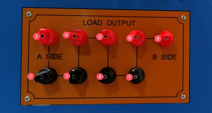
Connect them in series in the direction indicated by the black line in Figure 4-1. When the load current is high, use sufficiently thick connecting wires to ensure that the wires’ current-carrying capacity matches the test current and to prevent the wires from overheating.
If connecting only one sample, connect terminals ① and ⑨; if connecting two samples in series, connect the first sample to terminals ① and ②, and the second sample to terminals ② and ⑨; If you need to connect three samples in series, connect the first sample to terminals ① and ②, the second sample to terminals ② and ③, and the third sample to terminals ③ and ⑨. Continue in this manner.
Рассмотрим в качестве примера встраиваемую розетку. После подключения всех проводов она будет выглядеть как на изображении ниже. Необходимо замкнуть клеммы накоротко, чтобы создать тестовый ток для цепи.
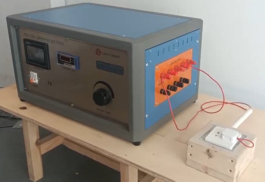
Примечание: Примерные монтажные работы и проводка должны соответствовать стандартным требованиям, чтобы предотвратить неплотные соединения проводов, которые могут привести к плохому контакту или искрению.
Select the key points to be measured (such as terminals, connectors, clamping elements, and housings). Securely attach the thermocouple of the Multiplex Temperature Tester to the measurement points using high-temperature-resistant tape or adhesive (such as Loctite 7452), ensuring tight contact with the sample surface and that there is no loosening.
4.4.2 Разминка оборудования
For safety reasons, first turn the test current adjustment knob on the front panel counterclockwise to the lowest setting. Then turn on the device’s power switch and let it warm up for 15 minutes before proceeding with the next steps.
5. Temperature Rise Test Procedure
5.1 Настройки параметров
Refer to Section 3.2.2 to configure the required test parameters. Note: To determine whether the test requires a power-on/power-off cycle and the duration of the test, please refer to the relevant standard requirements. Once the settings are complete, return to the test interface.
5.2 Debugging, Current Testing, and Startup Testing
| Номер регистрации | Внимание |
|---|---|
| ① | Tap “Test Power-On” on the touchscreen |
| ② | Turn the load current adjustment knob. Note: Adjust the current slowly to avoid sudden increases or decreases that could damage the equipment or sample. |
| ③ | Ensure that the real-time current displayed here meets the test requirements (please refer to the applicable standard to determine the specific current requirement). |
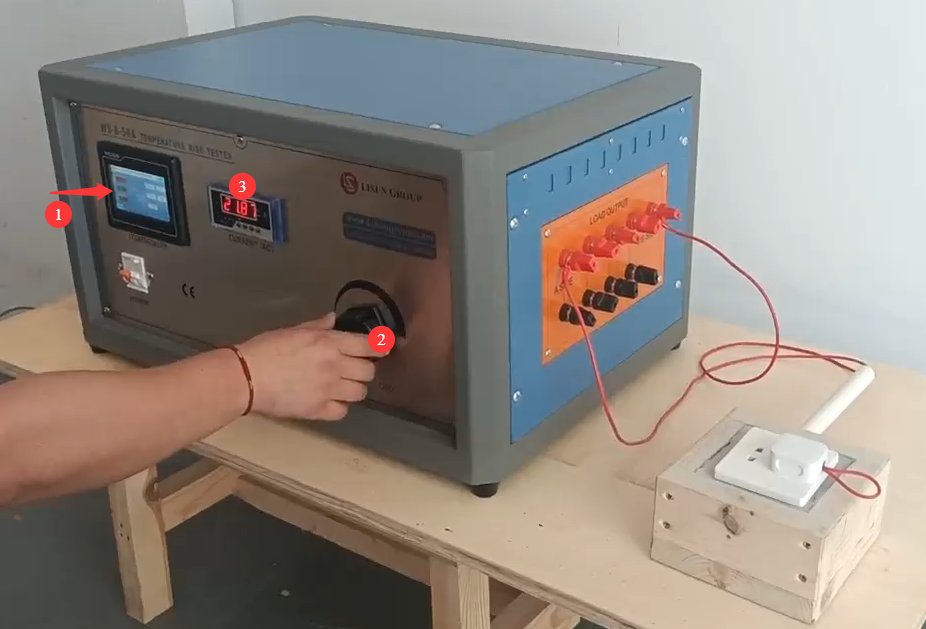
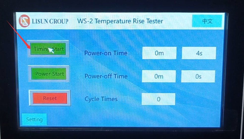
Once the test current has stabilized (fluctuation range ≤ ±0.5%), click “Start Timer” to begin the test, as shown in Figure 5-3.
5.3 Monitoring the Test Process
The Multiplex Temperature Tester software can record the initial temperature (when the power is off) and temperature changes during the test;
Monitor the load current display to ensure that the current remains stable within the test current range at all times. If abnormal current fluctuations occur, promptly investigate the cause (such as loose connections or poor contact with the sample);
If there is an abnormal spike in temperature or an alarm is triggered, stop the test immediately and investigate whether the problem lies with the sample or the equipment.
During the test, do not alter parameters, touch the wiring, or move the samples without authorization to ensure stable test conditions.
6. Процедуры после испытаний
6.1 Эксплуатация оборудования
6.1.1 Завершение теста
After the test is complete, wait for the device to automatically cut off the test current, or click “Start Test Power” again to manually cut off the test current;
Нажмите кнопку «Сброс» на сенсорном экране, чтобы удалить данные из этого теста и восстановить устройство до исходного состояния;
Slowly turn the test current adjustment knob counterclockwise to the lowest setting, then turn off the device’s power switch.
6.2 Обработка данных
6.2.1 Запись данных
Запишите данные о температуре до и после испытания (начальная температура, конечная температура и максимальное повышение температуры) и рассчитайте повышение температуры по следующей формуле: Повышение температуры (К) = Конечная температура (°C) – Начальная температура (°C);
Record the test current, test duration, number of cycles (if applicable), sample model and serial number, and test environment parameters (temperature, humidity), and compile this information into a test record form.
6.2.2 Интерпретация результатов
Comparison of temperature rise data from the comparative test with the standard limits:
① If the temperature rise is ≤ the standard limit, the sample is deemed to have passed the temperature rise test;
② If the temperature rise exceeds the standard limit, the sample is deemed non-compliant, and the cause of non-compliance must be analyzed (e.g., the connector sleeve is too thin, poor contact, insufficient wire cross-sectional area, etc.).
6.3 Sample and Equipment Preparation
6.3.1 Отбор проб
After the sample has cooled to room temperature, remove the load leads and thermocouples one by one. When removing them, avoid pulling on the wires with force to prevent damage to the sample or the thermocouples;
После проведения испытания осмотрите образец на наличие деформаций, следов обгорания или ослабленных соединений и запишите соответствующие данные.
6.3.2 Организация оборудования
Организуйте хранение таких принадлежностей, как термопары и соединительные провода, чтобы предотвратить их запутывание или повреждение;
Clean the surface of the equipment (wipe with a dry cloth; do not use water), remove any debris from the test area, and keep the environment tidy.
7. Плановое техническое обслуживание и уход
7.1 Short-Term Storage Requirements
Если оборудование используется ежедневно, после завершения очистки после каждого теста никаких дополнительных действий не требуется.
7.2 Требования к длительному хранению
Если устройство не будет использоваться в течение длительного периода (более одного месяца), пожалуйста, отсоедините все кабели и накройте устройство пылезащитным чехлом, чтобы предотвратить скопление пыли.
Для предотвращения износа электрических компонентов (таких как конденсаторы и контакторы) устройство следует включать раз в месяц и оставлять включенным на полчаса.
8. Устранение неполадок и решение распространенных проблем
8.1 Устройство не включается
8.1.1 Причины отказов
Шнур питания неправильно подключен или поврежден; отсутствует питание или напряжение ненормальное; предохранитель устройства перегорел; выключатель питания неисправен.
8.1.2 методов лечения
Check that the power cord is securely connected, the plug is firmly inserted, and the power cord is not damaged; if damaged, replace it. Use a multimeter to verify that the supply voltage is AC 220 V ± 10%; if there is no power, troubleshoot the power circuit; Check whether the fuse has blown; if so, replace it with a fuse of the same specification (never substitute it with another conductor). If none of the above issues are found, the power switch may be faulty; contact the manufacturer for repair.
8.2 The current cannot be adjusted or is unstable
8.2.1 Причины неисправностей
Повреждена ручка регулировки тока нагрузки; соединение проводов образца ослаблено или имеет плохой контакт; неисправен трансформатор напряжения; образец подключен неправильно или сам образец неисправен (например, обрыв цепи).
8.2.2 методов лечения
Check whether the knob rotates smoothly and if there is any sticking; replace it if damaged. Re-inspect the sample wiring, tighten any loose connections, check for short circuits, and replace any damaged sample wires; Disconnect the sample wiring and short-circuit the device’s sample terminals directly. If the current still cannot be adjusted or remains unstable, the Voltage Transformer may be faulty; contact the manufacturer for repair. Check whether the sample wiring meets specifications and whether the sample is functioning properly (e.g., no open circuits). Replace any faulty samples and try again.
8.3 Inaccurate Temperature Measurement or No Display
8.3.1 Причины отказов
The thermocouple is not properly connected or is damaged; the thermocouple is not making proper contact with the sample surface; the temperature measurement module is malfunctioning; the display shows an error.
8.3.2 методов лечения
Check whether the thermocouple is securely connected to the device interface; try unplugging and replugging it. If the thermocouple is broken or the insulation is damaged, replace it; Check whether the thermocouple’s sensing tip is in close contact with the sample; reattach it securely to ensure there is no play. Compare the measurement with a standard thermometer; if the deviation is too large, the temperature measurement module may be faulty—contact a calibration or repair service. If a single temperature channel shows no display, the interface for that channel may be faulty; try testing by switching to a different thermocouple interface.
8.4 Equipment Alarm Anomalies
8.4.1 Causes of Failures
Повышение температуры превышает установленный предел; истекло время тестирования; ненормальный ток (перегрузка).
8.4.2 методов лечения
If a temperature rise exceeds the limit: Immediately stop the test, check whether the sample is in good condition, verify that the thermocouple is positioned correctly, and confirm that the test parameters comply with the standard; after troubleshooting, repeat the test. If a time-out alarm is triggered: This is a normal occurrence; proceed according to the test completion procedure. If an abnormal current alarm is triggered: Check whether the current setting exceeds the rated value; after troubleshooting, reset the equipment.