
 Английский
 中文简体
中文简体 Русский
 Español
 Português
 Türkçe
 العربية
 Deutsch
 Polski
 Italiano
 Français
 한국어
한국어 ไทย
ไทย Tiếng Việt
 日本語
日本語





























Тестер пробивного напряжения переменного тока
Руководство пользователя
Применимый LISUN модели: WB2673A,WB2673B,WB2673C
1. Распаковка и базовое ознакомление с оборудованием.
1.1 Основные технические характеристики
| Модель / Технические характеристики | Диапазон испытательного напряжения | Диапазон тока пробоя | Мощность трансформатора напряжения | Продолжительность теста | Точность подачи |
| WB2673A | 0–5 kV (AC) | Переменный ток: 0–200 мА | 1 кВА | 1–99 XNUMX секунд | ± 5% |
| WB2673B | Переменный ток: 0–400 мА | 2 кВА | |||
| WB2673C | Переменный ток: 0–600 мА | 3 кВА |
1.2 Распаковка и проверка содержимого
1.2.1 Распаковка и визуальный осмотр
При распаковке устройства обращайтесь с ним осторожно, чтобы не поцарапать корпус острыми предметами. После распаковки сначала осмотрите внешний вид устройства, чтобы убедиться в отсутствии видимых деформаций или вмятин, а также в том, что кнопки не повреждены и не расшатаны. Если вы обнаружите какие-либо неисправности устройства или его аксессуаров, не включайте его. Немедленно свяжитесь с нами.
1.2.2 Основной блок и принадлежности
Хост: 1 хост WB2673.
Основные компоненты следующие:
| Номер регистрации | Внимание |
| ① | Шнур питания |
| ② | Test Power Cable |
| ③ | Зажим заземления |
| ④ | High-voltage rod, including a high-voltage rod connection cable and a remote control cable; the handheld end of the high-voltage rod includes control buttons |
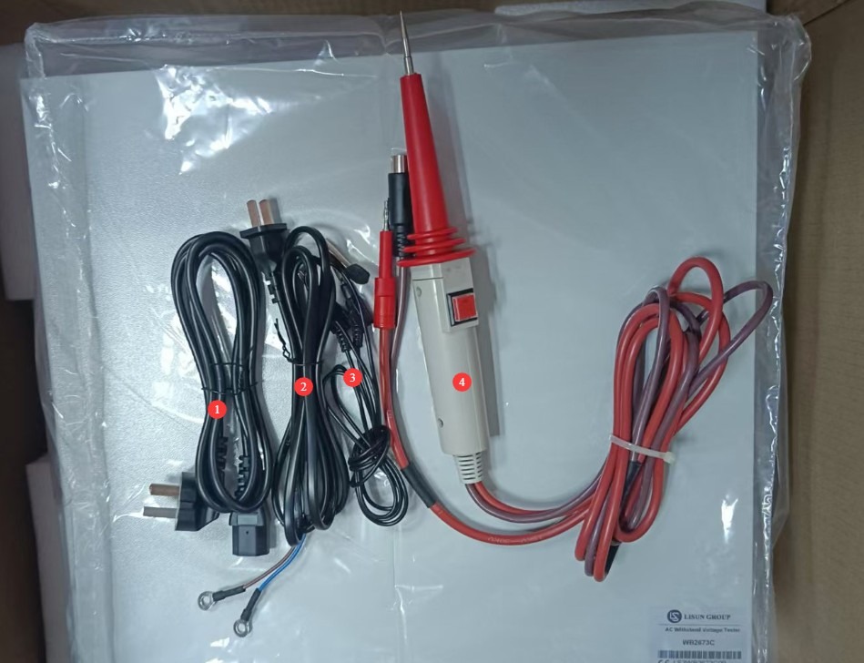
Рисунок 1
Ссылки для скачивания электронного руководства пользователя, программного обеспечения, гарантийного талона и других материалов были отправлены по электронной почте. Пожалуйста, скачайте их как можно скорее. Если вы пропустили письмо, пожалуйста, свяжитесь с нами, чтобы запросить ссылки для скачивания еще раз.
2 Меры безопасности
2.1 Электробезопасность
2.1.1 Требования к источнику питания
Используйте однофазную трехконтактную розетку переменного тока 220 В ±10%, 50/60 Гц; заземляющий контакт должен быть подключен к заземлению.
2.1.2 Требования к заземлению
The instrument ground wire is reliably connected to the protective ground wire, and the protective ground resistance is ≤4Ω;
Do not short-circuit the output terminals to the AC power source to prevent the enclosure from becoming energized.
2.2. Экологическая безопасность
2.2.1 Требования к температуре и влажности
Избегайте использования устройства в условиях влажности, превышающей 70% (без конденсации), или при температуре, выходящей за пределы диапазона 0–35 °C. Оптимальная рабочая температура составляет 25 ± 2 °C.
2.2.2 Противопоказания, связанные с окружающей средой
Среды с сильными магнитными и сильными электрическими полями;
Среды, содержащие коррозионные газы или жидкости;
Areas with flammable and explosive dust or hazardous materials;
Среда с высокой запыленностью, высокими температурами и влажностью, а также прямыми солнечными лучами.
2.3 Эксплуатационная безопасность
Во время испытаний корпус испытуемого объекта заряжается электрическим током; ни при каких обстоятельствах не прикасайтесь к нему голыми руками;
The test object must be placed on a rubber insulating mat;
Операторы должны носить резиновые перчатки с теплоизоляцией;
Никогда не замыкайте накоротко выходной клеммный разъем высокого напряжения (высоковольтный щуп) непосредственно на клемму заземления (заземляющий зажим), так как это может привести к перегоранию внутреннего трансформатора напряжения;
Операторы должны иметь сухие руки и не носить металлические украшения; во время испытаний запрещено есть и пить, чтобы предотвратить несчастные случаи, вызванные поражением электрическим током.
Перед заменой тестируемого объекта необходимо сначала остановить тестирование и убедиться, что выходное напряжение устройства равно 0;
Если в тестировании участвует несколько человек, четко определите роли и обязанности и подтвердите их друг с другом до начала тестирования, чтобы избежать ошибок.
Другие 2.4
По вопросам, не охваченным данным руководством, пожалуйста, проявляйте осторожность или свяжитесь с нами.
3. Обзор оборудования
3.1 Введение в переднюю панель оборудования
| Номер регистрации | Внимание |
| ① | Выключатель |
| ② | High-voltage output connector, used to connect to the live parts of the device under test |
| ③ | Remote-controlled outlet; remote control wire connected to the high-voltage rod |
| ④ | Подключите заземляющие клещи; используйте штекер типа «банан» для подключения к прибору, а конец клещей — для подключения к тестируемому устройству. |
| ⑤ | Test Time Settings: You can set the test duration from 1 to 99 seconds for use with a timer switch. |
| ⑥ | Время тестирования отображается в секундах. Примечание: Доступно только при включенном переключателе таймера. |
| ⑦ | Окно отображения тока утечки: отображает пороговое значение тревоги в режиме ожидания и ток утечки в реальном времени в тестовом режиме, в миллиамперах. |
| ⑧ | Окно отображения выходного напряжения, показывающее текущее значение высоковольтного выходного напряжения в кВ. |
| ⑨ | Индикатор состояния тестирования: TE: Тестирование; NG: Ток утечки превышает пороговое значение + звучит звуковой сигнал. |
| ⑩ | Current adjustment knob: Sets the alarm current threshold; used in conjunction with the alarm selection button. |
| ⑪ | Переключатель «Предварительная настройка/Тест»: Нажмите, чтобы войти в режим предварительной настройки; нажмите вверх, чтобы войти в тестовый режим. |
| ⑫ | Timer switch: Press to enable the timer; release to disable it. |
| ⑬ | Residual Current Range Selection Button; the ranges are interlocked, so only one range can be selected at a time. |
| ⑭ | Ручка регулировки выходного напряжения: поверните по часовой стрелке для увеличения выходного напряжения; поверните против часовой стрелки для его уменьшения. |
| ⑮ | Нажмите кнопку «Старт», чтобы начать проверку; индикатор проверки загорится. |
| ⑯ | Кнопка сброса: отключает выходное напряжение, останавливает тестирование и сбрасывает сигнал тревоги. |
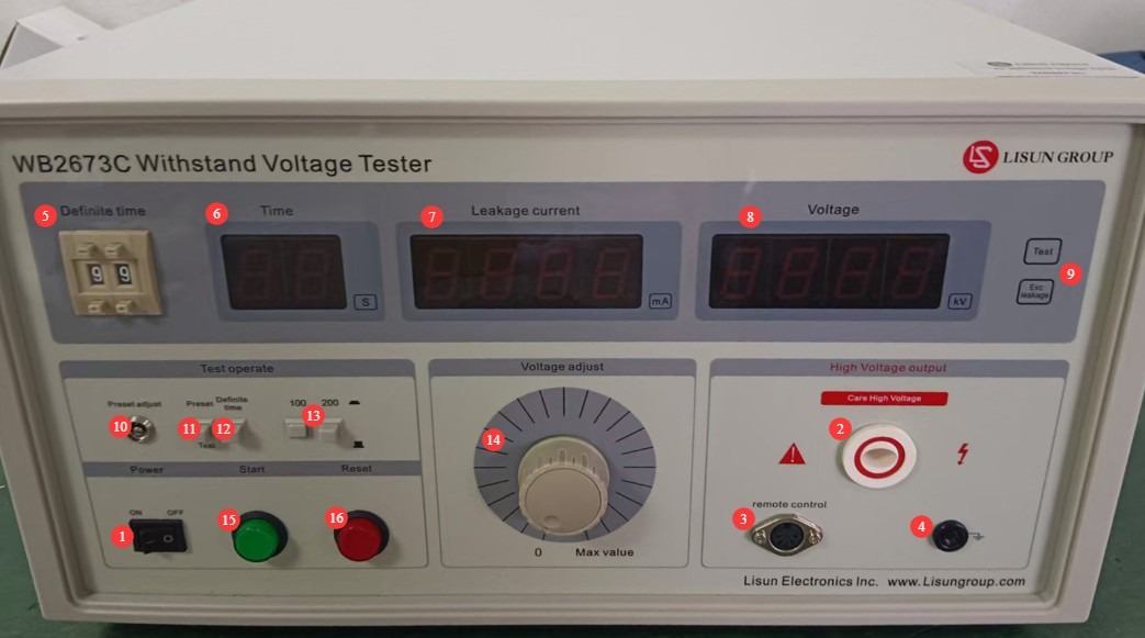
Рисунок 2
Примечание: После подключения кабеля дистанционного управления кнопки питания и перезагрузки на передней панели устройства работать не будут.
3.1 Introduction to the Equipment Back Panel
| Номер регистрации | Внимание |
| ① | Power cord receptacle, with built-in fuse |
| ② | To connect the test power supply terminals, use the test power supply connection cable to connect to a 220 V AC ±10%, 50/60 Hz power source. |
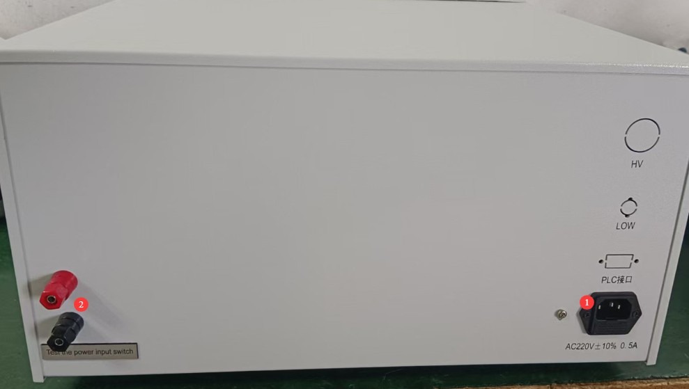
Рисунок 3
4. Подготовка перед тестированием
4.1 Включение оборудования
Plug the power cord into a standard three-prong outlet, press the power switch, and the instrument’s display will light up. The TE and NG indicator lights will be off, and the leakage current and voltage displays will show 0. If there are no abnormal audible or visual alarms, this indicates that the device’s power-on self-test was successful.
4.2 Подготовка испытательного образца
Корпус испытуемого объекта должен быть чистым и без следов масла; поместите его в центр изолирующего мата, подальше от металлической рабочей поверхности.
5. Процедура испытаний
5.1 Предварительные настройки параметров тестирования
All parameter presets must be completed by following the steps below, with the high-voltage rod, remote control cable, and grounding clamps removed.
5.1.1 Selection of Leakage Current Range
Select the appropriate leakage current range button based on the standard requirements for the test item.
5.1.2 Установка порогового значения срабатывания сигнализации о токе утечки
Switch the Preset/Test button to the preset state.
Slowly turn the current adjustment knob while observing the leakage current display window, and adjust the value to the alarm threshold specified in the test item’s standards.
Once the settings have been configured, switch the Preset/Test button to the Test mode; the leakage current display will return to 0, and the alarm value will be automatically saved.
5.1.3 Установка продолжительности теста
Выберите ручной режим или режим таймера в соответствии с требованиями стандарта тестирования:
Manual Mode: Flip the timer switch to the “On” position; there is no need to set a time—the operator manually controls the test duration.
Timer Mode: Press the timer switch to set the test duration to the required length (1–99 seconds); the time will be displayed as a countdown.
5.1.4 Настройка выходного напряжения
Press the Start button and observe the value displayed in the output voltage display window. You can adjust it to the standard required value by turning the output voltage adjustment knob. Once adjusted, press the Reset button.
Примечание: Для испытаний с заданными скоростями нарастания напряжения не устанавливайте напряжение предварительно; просто поверните ручку в положение 0. После официального начала испытания медленно поворачивайте ручку, чтобы отрегулировать выходное напряжение до тестового напряжения со скоростью, указанной в стандарте.
5.2 Подключение оборудования
| инструкции | Внимание |
| ① | Insert the banana plug end of the grounding clamp into the instrument’s connector, and verify that the ground terminal or metal casing of the device under test is securely connected to the clamp’s grounding terminal. |
| ② | Надежно вставьте кабель дистанционного управления высоковольтным стержнем в соответствующий разъем на главном блоке. |
| ③ | Securely connect the high-voltage probe cable to the AC high-voltage output port on the main unit, and keep the high-voltage probe’s output end away from the test object for the time being. |
5.3 Испытание на выдерживаемое напряжение
5.3.1 Тестирование при запуске
Place the output end of the high-voltage probe in close contact with the live parts of the test object (such as the power cord input or the winding leads). Then press the output control button on the high-voltage probe to begin the test.
5.3.2 Завершение тестирования
В режиме таймера по окончании обратного отсчета высокое напряжение автоматически отключается, и тестирование прекращается; в ручном режиме тестирование прекращается при отпускании кнопки управления высоковольтным щупом.
If any of the following abnormalities occur during testing, the test must be stopped immediately: smoke, unusual noises, or sparks from the test item; unusual noises, strange odors, or a black screen on the display. After an emergency stop, investigate the cause of the abnormality; do not resume testing until the problem has been resolved.
5.4 Оценка результатов испытаний
Результаты испытаний оцениваются в первую очередь по наличию пробоя и по тому, превышает ли ток утечки пороговое значение.
5.4.1 Критерии приемки
Throughout the entire test, the voltage remained stable at the standard requirement value, and the real-time leakage current remained below the set alarm threshold at all times; the “NG” indicator light and buzzer alarm were not triggered.
5.4.2 Критерии определения несоответствия
During testing, if the leakage current exceeds the alarm threshold, the “NG” light turns on and the buzzer sounds.
Испытуемый образец демонстрирует явные признаки пробоя, пробоя, задымления и т. д.
6. Ежедневное техническое обслуживание и уход за оборудованием.
6.1 Текущее обслуживание
Before turning on the equipment, check to ensure that the exterior is clean and undamaged, that the cables show no signs of aging or breakage, and that the connectors are secure; Check the grounding clamps for oxidation or burn marks; if present, wipe them with a specialized contact cleaner, and contact us to replace parts if necessary; after testing is complete, disconnect the power and wipe down the equipment surface and the test area with a dry, antistatic cloth.
6.2 Долгосрочное хранение
When the device is not in use for an extended period, store it in a dry, well-ventilated environment, away from moisture and direct sunlight; disconnect all cables, store accessories separately, and cover the device with a dust-proof cloth; turn the device on for 30 minutes once a month to prevent the internal electronic components from deteriorating.
7. Поиск и устранение распространенных проблем
| Признаки неисправности | Возможные причины | Метод |
| Устройство не включается | The power cord isn’t plugged in securely; the fuse has blown. | Check the power cord connections; check the fuse in the device’s power input port; if it is blown, replace it with a fuse of the same type. |
| After startup, the display flickers and the keys do not respond. | Нестабильное напряжение питания | Use a multimeter to measure the supply voltage and verify that it is within the range of AC 220 V ±10%. If the voltage is unstable, install a voltage regulator. |
| Unjustified alarms during testing | Неправильный выбор диапазона тока утечки; неправильная установка порогового значения тока срабатывания сигнализации. | Сначала выберите правильный диапазон тока утечки, а затем отрегулируйте пороговое значение тока срабатывания сигнализации. |
Appendix A: Summary Table of AC Withstand Voltage Test Requirements in Relevant Standards
| Стандартный номер | Виды рассматриваемой электронной продукции | Dielectric Withstanding Voltage Test Requirements | Breakdown Current / Leakage Current Limits | Продолжительность теста | Other Testing Requirements |
| GB/T 24344-2009/IEC 60204-1:2021 | Electrical and electronic equipment and systems for industrial machinery; electrical systems for machinery with a rated voltage of ≤1000 V AC or 1500 V DC | 1. Basic insulation: 2 × rated voltage + 1000 V, with a minimum of 1500 V AC; 2. Rated voltage ≤ 60 V: 500 V AC; 3. 60 V < rated voltage ≤ 300 V: 1000 V AC; 4. 300 V < rated voltage ≤ 690 V: 1500 V AC; 5. Frequency: AC voltage between 45 Hz and 65 Hz, with a waveform approximating a sine wave, and a peak-to-root-mean-square (RMS) ratio within √2 ± 0.07 | The test is considered successful if there are no breakdowns or flashovers; leakage current serves as a supplementary evaluation criterion, and there is no specific fixed limit. | 1. Standard test: 1 minute; 2. Rapid test: at least 1 second (as specified in IEC 60204-1:2021) | 1. The test voltage should start at 0 and be increased uniformly to the specified value; avoid sudden voltage increases; 2. After the test, slowly reduce the voltage to zero; 3. Applicable to dielectric strength tests for industrial machinery and electrical equipment, covering protection against electric shock, equipment protection, and more. |
| GB 4706.1-2024/IEC 60335-1:2023 | Household and similar electrical appliances with a rated voltage not exceeding 250 V for single-phase appliances and 480 V for other appliances, including refrigerators, air conditioners, electric irons, blenders, and other types of home appliances | 1. Basic insulation: 1000 V + 2× rated voltage, minimum 1500 V AC; 2. Reinforced insulation: 2000 V + 4× rated voltage, minimum 3000 V AC;3. Class 0 and Class I appliances: 1250 V AC; 4. Class II appliances: 1750 V AC; 5. Frequency: 50 Hz/60 Hz power-frequency sine wave | 1. The test is considered satisfactory if no breakdown, arcing, or flashover occurs during the test; 2. The high-voltage power supply must be capable of supplying the specified short-circuit current when a short circuit occurs at the output;3. Leakage current limits: 0.25 mA for Class II equipment; 0.5 mA for Class 0, Class I, and Class III equipment | 1. Routine testing: 1 minute; 2. In special cases, follow the specific provisions of the standard. | 1. The test shall be conducted at room temperature; for Class 0 and Class I appliances, a moisture treatment must be performed prior to the test; 2. For Class II designs that feature both reinforced insulation and double insulation, care must be taken to ensure that the voltage applied to the reinforced insulation does not cause excessive stress on the basic insulation or supplementary insulation;3. When testing the insulating covering, sandbags may be used to apply a pressure of approximately 10 kPa. |
| GB 19212.1-2021/IEC 61558-1:2022 | Voltage Transformers, reactors, power supply units, and their combined products, including Isolation Transformers, safety isolation transformers, autotransformers, and variable transformers; switching power supplies, inductive ballasts, chargers, etc., with a rated voltage not exceeding 1000 V AC or 1500 V DC. National Standard Information Public Service Platform | 1. Between windings and between windings and the housing: 2500 V to 4000 V AC (determined based on the insulation class and rated voltage);2. Basic insulation: 1000 V + 2× rated voltage; 3. Reinforced insulation: 2000 V + 4× rated voltage; 4. Frequency: 50 Hz/60 Hz power-frequency voltage | The test is considered satisfactory if no breakdown or arcing occurs; the leakage current must comply with the product-specific safety requirements. | 1 minute (60 seconds) | 1. The test voltage shall be gradually increased to the specified value within 5 seconds; 2. Applies to general safety requirements for Voltage Transformers, reactors, power supply units, and combinations thereof; 3. Emphasizes the ability to maintain protection against electric shock, overheating, and mechanical injury even under single-fault conditions |