
 Английский
 中文简体
中文简体 Русский
 Español
 Português
 Türkçe
 العربية
 Deutsch
 Polski
 Italiano
 Français
 한국어
한국어 ไทย
ไทย Tiếng Việt
 日本語
日本語





























Испытание выдерживаемого напряжения и изоляции
Руководство пользователя
Применимый LISUN модели: LS9923
1. Распаковка и базовое ознакомление с оборудованием.
1.1 Основные технические характеристики
| Параметры | Внимание | |
| Испытания на выдерживаемое напряжение переменного и постоянного тока | Диапазон выходного напряжения | AC/DC 0–5.00 kV |
| Точность выходного напряжения | ± (3% + 3 цифр) | |
| Диапазон тока пробоя | AC: Max 20 mA; DC: Max 10 mA | |
| Время тестирования | 0–999.9 с | |
| Выходная частота | 50 Гц / 60 Гц | |
| Испытание сопротивления изоляции | Диапазон выходного напряжения | DC 0–1.00 kV |
| Точность выходного напряжения | ± (2% + 3 цифр) | |
| Диапазон сопротивления изоляции | 1.0–2000 МОм | |
| Точность сопротивления изоляции | ±(5% + 3 digits) < 100 MΩ and ±(10% + 5 digits) > 100 MΩ | |
| Время тестирования | 0–999.9 с | |
1.2 Распаковка, осмотр и проверка аксессуаров
1.2.1 Распаковка и визуальный осмотр
При распаковке устройства обращайтесь с ним осторожно, чтобы не поцарапать корпус острыми предметами. После распаковки сначала осмотрите внешний вид устройства, чтобы убедиться в отсутствии видимых деформаций или вмятин, а также в том, что кнопки не повреждены и не расшатаны. Если вы обнаружите какие-либо неисправности устройства или его аксессуаров, не включайте его. Немедленно свяжитесь с нами.
1.2.2 Основной блок и принадлежности
Хост: 1 LS9923 хост.
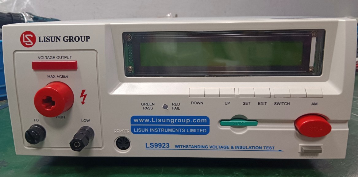
Рисунок 1
Основные компоненты следующие:
| Номер регистрации | Внимание |
| ① | Шнур питания |
| ② | High-voltage rod, including high-voltage rod connection cable and remote control cable; the handheld end of the high-voltage rod includes control buttons |
| ③ | Зажим заземления |
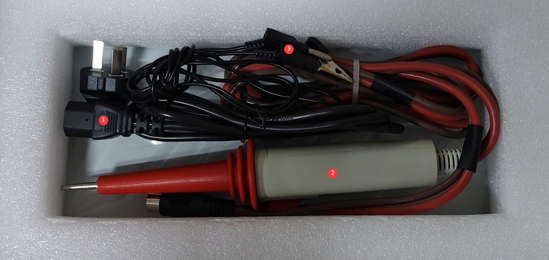
Рисунок 2
Ссылки для скачивания цифрового руководства пользователя, программного обеспечения, гарантийного талона и других материалов были отправлены по электронной почте. Пожалуйста, скачайте их как можно скорее. Если вы пропустили письмо, пожалуйста, свяжитесь с нами, чтобы получить ссылки для скачивания повторно.
2 Меры безопасности
2.1 Электробезопасность
2.1.1 Требования к источнику питания
Используйте однофазную трехконтактную розетку переменного тока 220 В ±10%, 50/60 Гц; заземляющий контакт должен быть подключен к заземлению.
2.1.2 Требования к заземлению
Провод заземления прибора надежно соединен с защитным проводом заземления, а сопротивление защитного заземления составляет ≤4 Ом;
Do not short-circuit the output terminal to the AC power source to prevent the enclosure from becoming energized.
2.2. Экологическая безопасность
2.2.1 Требования к температуре и влажности
Avoid using the device in environments where humidity exceeds 70% (without condensation) or where temperatures fall outside the range of 0–35°C. The optimal operating temperature is 25 ± 2°C.
2.2.2 Противопоказания, связанные с окружающей средой
Среды с сильными магнитными и сильными электрическими полями;
Среды, содержащие коррозионные газы или жидкости;
Areas with flammable and explosive dust, and locations containing hazardous materials;
Среда с высокой запыленностью, высокими температурами и влажностью, а также прямыми солнечными лучами.
2.3 Эксплуатационная безопасность
During testing, the outer casing of the test object is electrically charged; do not touch it with your bare hands under any circumstances;
Испытуемый образец необходимо поместить на резиновый изоляционный коврик;
Операторы должны носить резиновые перчатки с теплоизоляцией;
Operators must have dry hands and must not wear metal jewelry; eating or drinking is prohibited during testing to prevent accidents caused by electric shock;
Перед заменой тестируемого объекта необходимо сначала остановить тестирование и отключить тестируемый объект от источника питания;
When multiple people are involved, clearly define roles and responsibilities, and confirm them with one another before testing begins to avoid errors.
Другие 2.4
По вопросам, не охваченным данным руководством, пожалуйста, проявляйте осторожность или свяжитесь с нами.
3. Эксплуатация оборудования
3.1 Настройки параметров
Предпосылки 3.1.1
To ensure operational safety, parameter settings cannot be made while the high-voltage rod and remote control cable are connected to the device. Please remove the high-voltage rod and remote control cable before configuring the parameters.
3.1.2 Setting Test Parameters in Automatic Mode
| Номер регистрации | Внимание |
| ① | Press the AM button to switch the device to automatic mode. |
| ② | Test groups marked with an asterisk after the letter are in manual mode; those without an asterisk are in automatic mode. |
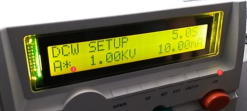
Рисунок 3
| Номер регистрации | Внимание |
| ① | Use the up and down arrows to switch between test groups. |
| ② | Up to seven sets of test parameters (A through G) can be saved. For each set, different parameters can be configured to perform ACW (AC Withstand Voltage)/DCW (DC Withstand Voltage) and IR (Insulation Resistance) tests. Note: Only one of ACW or DCW can be selected within the same test set; if both are selected, only DCW and IR will be performed during actual operation. |
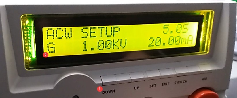
Рисунок 4
| Номер регистрации | Внимание |
| ① | Нажмите кнопку SET |
| ② | Use the up and down arrows to select a test item. |
| ③ | ACW, DCW, and IR |
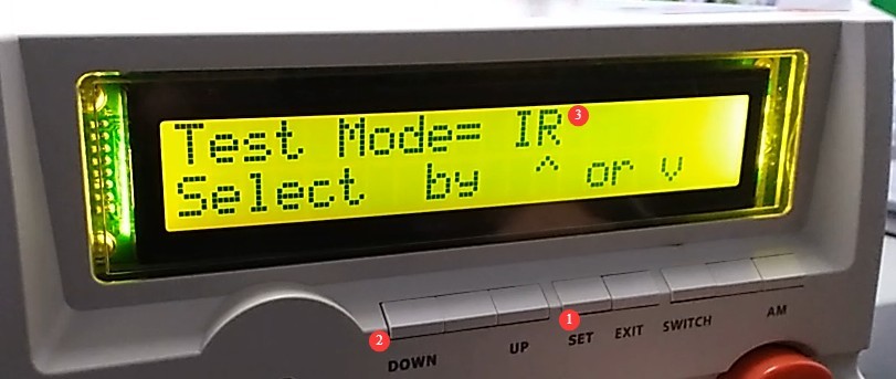
Рисунок 5
After selecting IR, press the SET button again to configure the IR test parameters. Note: All specific parameters can be set using the up and down buttons. Once a parameter is set, press the SET button again to configure the next item.
Test voltage settings.
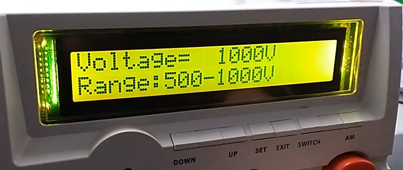
Рисунок 6
Установка верхнего предела.
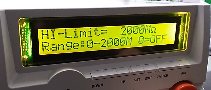
Рисунок 7
Lower limit setting.
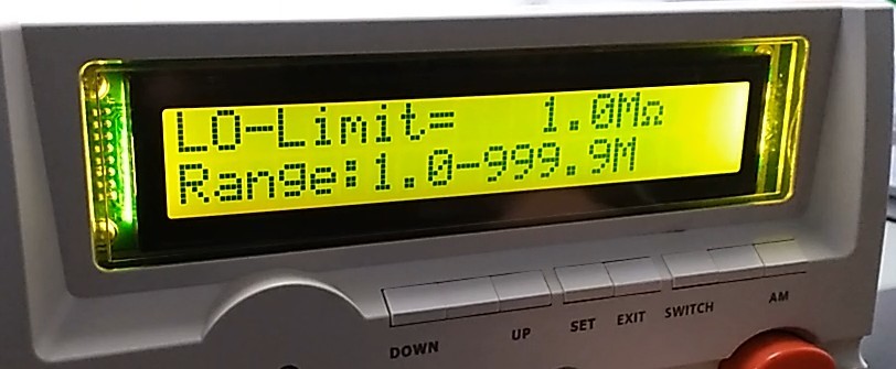
Рисунок 8
Test Duration Settings.
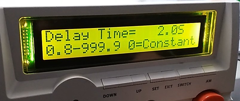
Рисунок 9
Sound Alert Settings.
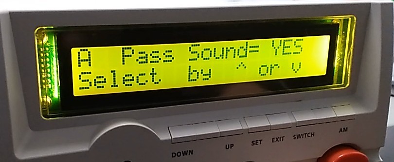
Рисунок 10
Select whether to run the IR test.
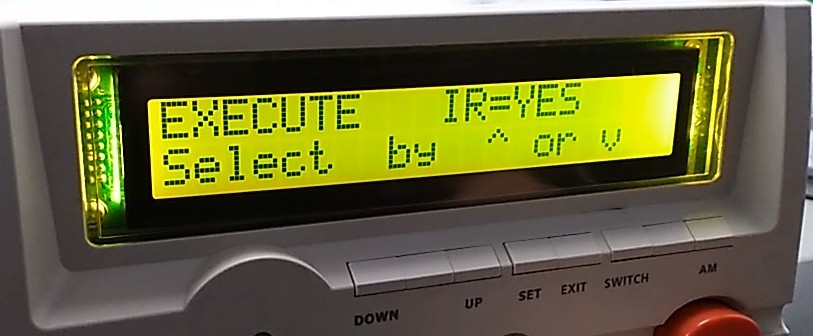
Рисунок 11
Switch the test mode to ACW.
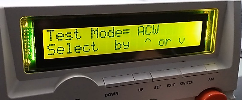
Рисунок 12
Test Voltage Settings.
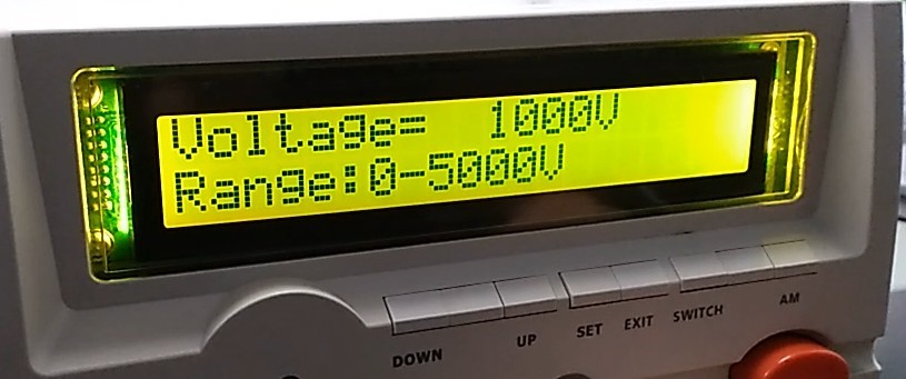
Рисунок 13
Установка верхнего предела.
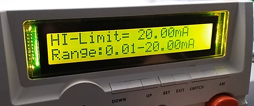
Рисунок 14
Lower limit setting.
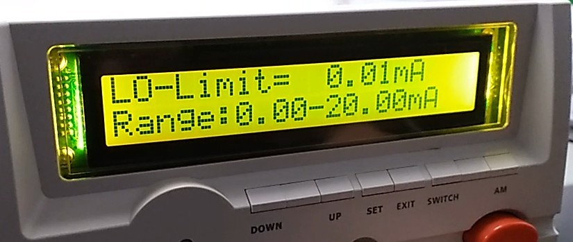
Рисунок 15
Rise time setting: the time required for the test voltage to rise from 0 to the set value.
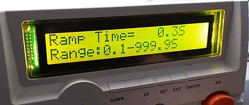
Рисунок 16
The test took a long time.
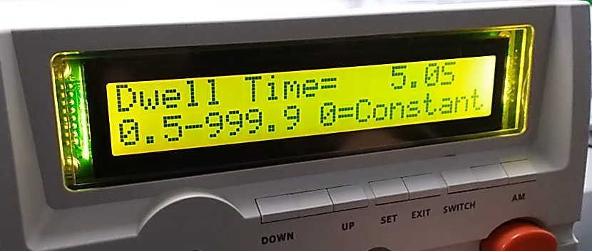
Рисунок 17
Frequency settings.
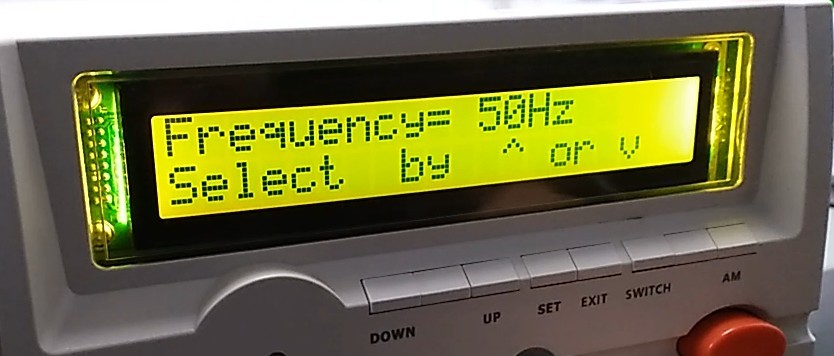
Рисунок 18
Arc detection function. 0 means no detection; 0 through 9 indicates detection sensitivity ranging from low to high.
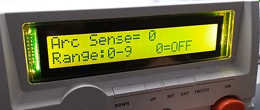
Рисунок 19
Sound Alert Settings.
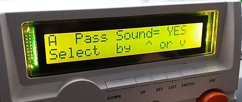
Рисунок 20
Select whether to run the ACW test.
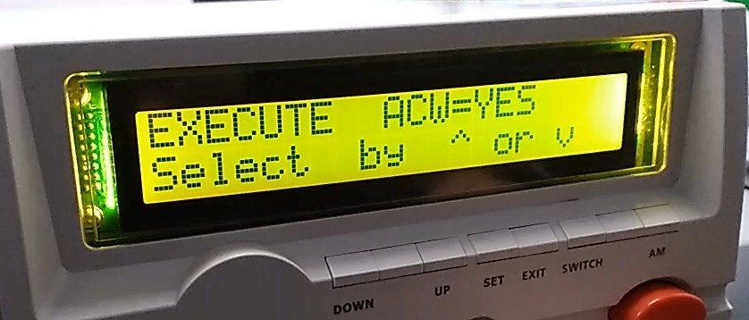
Рисунок 21
Switch the test mode to DCW.
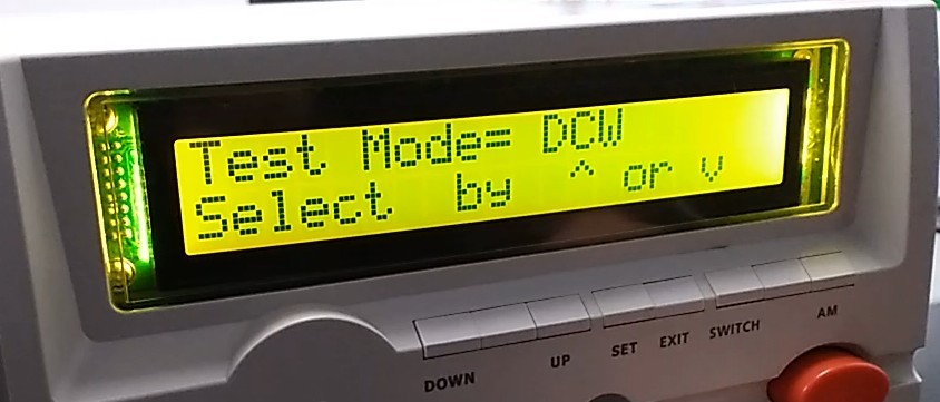
Рисунок 22
Test Voltage Settings.
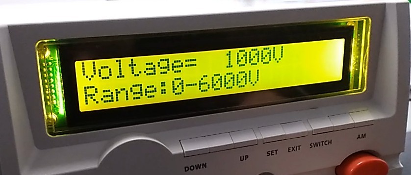
Рисунок 23
Установка верхнего предела.
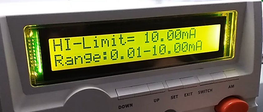
Рисунок 24
Lower limit setting.
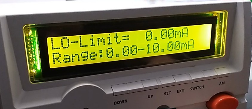
Рисунок 25
Rise time setting: the time required for the test voltage to rise from 0 to the set value.
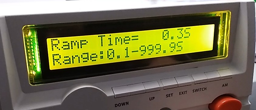
Рисунок 26
Test Duration Settings.
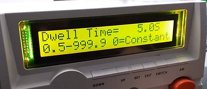
Рисунок 27
Arc detection function. 0 means no detection; values from 0 to 9 indicate detection sensitivity ranging from low to high.
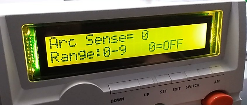
Рисунок 28
Sound Alert Settings.
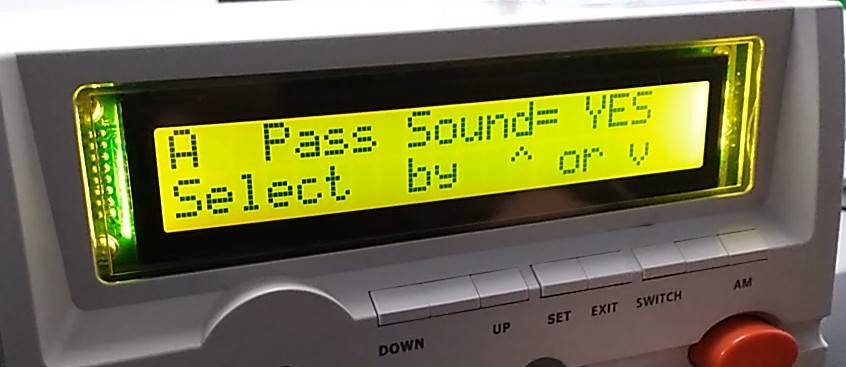
Рисунок 29
Select whether to run the DCW test.
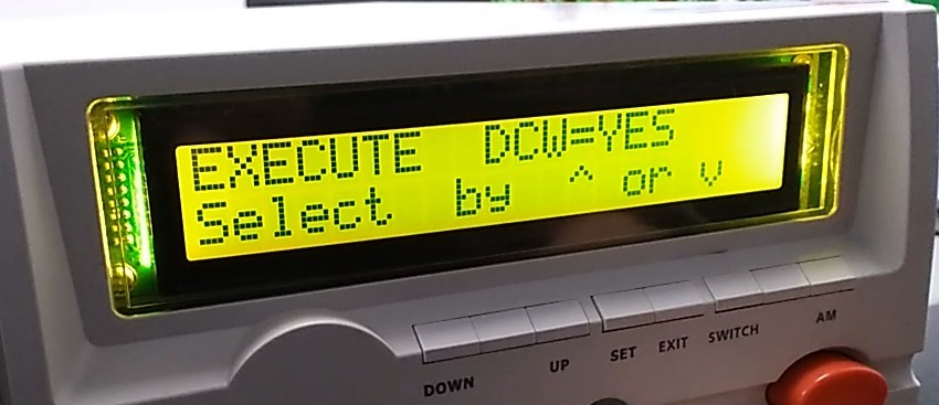
Рисунок 30
Once all settings are complete, press EXIT to return to the initial screen.
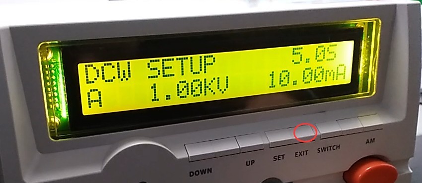
Рисунок 31
Note: Using GB/T 7000.1-2023 as an example, the following settings can be configured.
| Тестовые задания | Соответствующие стандартные положения | Настройки параметров теста | Допустимые пределы | Время тестирования |
| Испытание сопротивления изоляции | 10.2 | Испытательное напряжение: 500 В постоянного тока. | ≥2 МОм | 60s |
| Испытание диэлектрической прочности (напряжения пробоя) | Испытательное напряжение: 1500 В переменного тока. | Отсутствие пробоя, отсутствие пробоя через электрическую пластину; ток утечки ≤ 5 мА |
3.1.3 Introduction to Manual Mode
If the current test group is A, press the AM key to switch to Manual Mode A*. Manual Mode A* runs only the current test in test group A. If it is an IR test, press the SWITCH key to switch to ACW/DCW testing (provided that test group A is configured to perform ACW/DCW and IR tests simultaneously). Test parameters cannot be modified in manual mode; only the SWITCH and AM keys are available.
That is: In automatic mode, when a test is run, all test items configured in that test group are executed sequentially; in manual mode, when a test is run, only the current test item in that test group is executed.
3.2 Эксплуатационные испытания
3.2.1 Обзор передней панели и схема подключения
| инструкции | Внимание |
| ① | First, connect the ground clamp cable. |
| ② | Reconnect the remote control cable |
| ③ | Finally, connect the high-voltage rod cable |
| ④ | Start button—press to begin the test |
| ⑤ | Stop button: Press to stop the test |
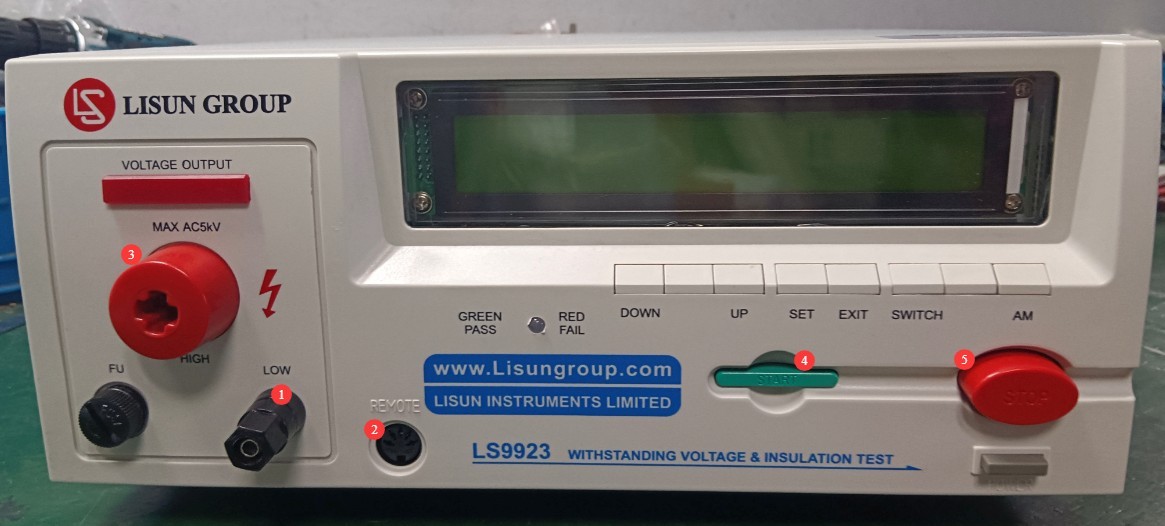
Рисунок 32
Note: Once the remote control cable is plugged in, the Start and Stop buttons on the device’s front panel will be disabled.
3.2.2 Подключение тестового объекта
Корпус испытуемого объекта должен быть чистым и без следов масла; поместите его в центр изолирующего мата, подальше от металлической рабочей поверхности.
Taking a light fixture as an example, attach the grounding clamp to the fixture’s ground wire, and use the high-voltage tester to test the fixture’s power line (L or N).
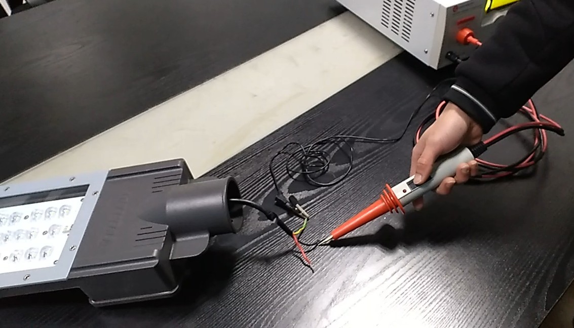
Рисунок 33
3.2.3 Тестирование при запуске
Press the Start button or the control button on the high-voltage probe to start the test; press the Stop button or release the control button on the high-voltage probe to stop the test.
3.2.4 Просмотр результатов теста
If the test continues until it completes normally, it is considered passed. If any single test item fails, the test stops automatically, and the screen displays the failed test item. Please check whether the issue is due to the parameter settings or the test specimen itself.
4. Ежедневное техническое обслуживание и уход за оборудованием.
4.1 Текущее обслуживание
Before powering on, inspect the equipment to ensure it is clean and free of damage, that the cables show no signs of aging or breakage, and that the connectors are secure; Check the grounding clamps for oxidation or burn marks; if present, wipe them with a specialized contact cleaner, and contact us to replace parts if necessary; after testing is complete, disconnect the power and wipe the equipment surface and test area with an anti-static, dry cloth.
4.2 Долгосрочное хранение
Когда устройство не используется в течение длительного времени, храните его в сухом, хорошо проветриваемом месте, вдали от влаги и прямых солнечных лучей; отсоедините все кабели, храните аксессуары отдельно и накройте устройство пылезащитной тканью; включайте устройство на 30 минут каждый месяц, чтобы предотвратить износ внутренних электронных компонентов.
5. Поиск и устранение распространенных проблем
| Признаки неисправности | Возможные причины | Метод |
| Устройство не включается | Шнур питания неплотно вставлен; предохранитель перегорел. | Проверьте соединения шнура питания; проверьте предохранитель в разъеме питания устройства; если он перегорел, замените его предохранителем той же модели. |
| Some buttons aren’t responding | The device is in an inappropriate test mode | In Auto mode, the SWITCH button is unavailable; in Manual mode, only the SWITCH and AM buttons are available. |