
 Английский
 中文简体
中文简体 Русский
 Español
 Português
 Türkçe
 العربية
 Deutsch
 Polski
 Italiano
 Français
 한국어
한국어 ไทย
ไทย Tiếng Việt
 日本語
日本語





























Устройство для испытания покрытия на устойчивость к царапинам
Руководство пользователя
Применимый LISUN модели: LS-B30
1. Распаковка и базовое ознакомление с оборудованием.
1.1 Основные технические характеристики
Scratch Steel Needle: Hardened steel needle with a tapered tip; the tip has a 40-degree angle with a fillet radius of 0.25 ± 0.02 mm.
Scratch angle: The stylus moves perpendicular to the test specimen surface; the forward scratching angle is 80° to 85°. Axial force on the steel stylus during the
coating scratch resistance test: 10 N ± 0.5 N.
Scratching length: up to 140 mm
. Translational distance: Maximum
200 mm Scratching speed: 20 mm/s ± 2 mm/s (adjustable)
1.2 Распаковка
1.2.1 Распаковка и визуальный осмотр
Before opening the box, check the outer packaging for any damage, deformation, or signs of moisture. After opening the box, remove the packing materials and inspect the exterior of the equipment for any damage, such as dents, scratches, or loose parts. If any of the above issues are found, please document them immediately and contact us.
1.2.2 Основной блок и принадлежности
Coating Scratch Resistance Test Device Main Unit: 1 unit.
For safety reasons, the equipment is shipped in separate packages. The key components include: one hardened steel pin, one 10N standard weight, a sample support plate, and one power cord.
Ссылки для скачивания цифрового руководства пользователя, гарантийного талона и других документов были отправлены вам по электронной почте. Пожалуйста, скачайте их как можно скорее. Если вы пропустили письмо, пожалуйста, свяжитесь с нами, чтобы запросить ссылки для скачивания еще раз.
1.3 Equipment Assembly and Structural Description
① Power cord socket; ② Circuit breaker; ③ Power switch; ④ Touchscreen; ⑤ Counterweight; ⑥ Sample support platform; ⑦ Weights; ⑧ Steel pin; ⑨ Sample for demonstration.
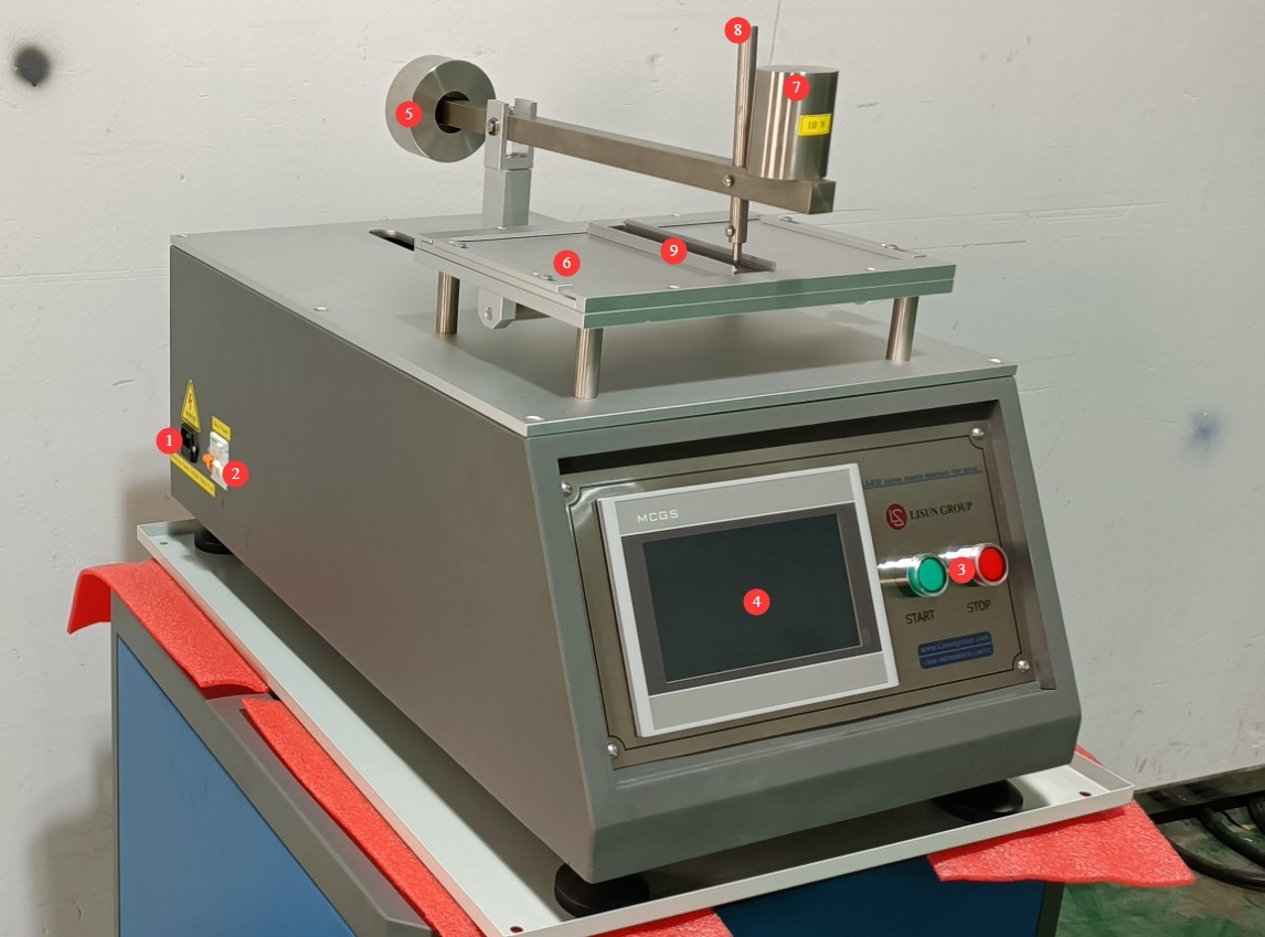
Рисунок 1
The knob shown in the figure below allows you to move the sample stage and the sample on the stage.
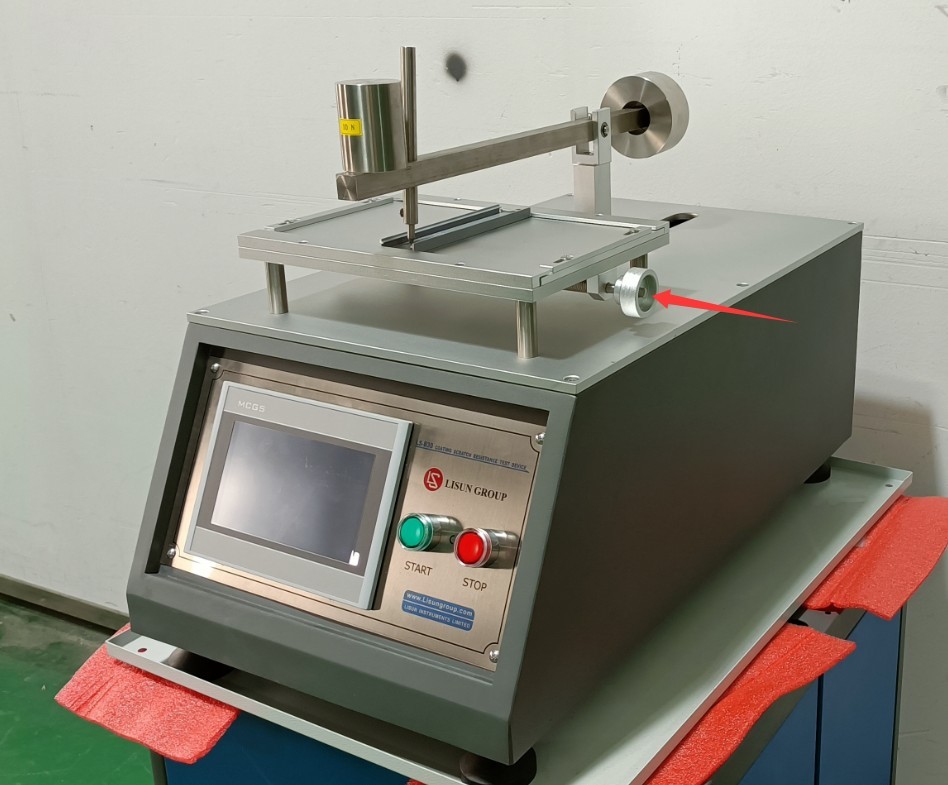
Рисунок 2
2. Меры предосторожности.
2.1 Электробезопасность
2.1.1 Требования к подключению питания
You must use a separate 220V AC power source that meets the equipment specifications, and the power outlet must be properly grounded.
Before connecting the power cord, make sure the device’s power switch is turned off. When plugging in the cord, ensure it is fully inserted to prevent a loose connection.
2.1.2 Электробезопасность
Do not touch electrical components such as power connectors or internal circuits while the equipment is in operation to prevent electric shock.
If you notice that the power cord is damaged or worn, stop using the device immediately and replace it with a certified power cord before resuming operation.
The test environment must be kept dry; keep water sources and damp items away from the equipment’s electrical components.
2.2 Эксплуатационная безопасность
While the equipment is in operation, do not reach into the area where the steel needles move or around the sample support platform with your hands, tools, or other objects to prevent pinching or scratches.
When manually operating the forward and reverse functions, adjust the speed gradually and observe whether the machine is operating normally to prevent components from colliding.
2.3 Требования к окружающей среде
The equipment must be placed on a level, stable work surface with no obstacles nearby to ensure sufficient space for the mechanical components to move.
The operating environment temperature should be maintained between 15°C and 35°C, with relative humidity ≤ 75%, and free of corrosive gases and dust.
3. Подготовка к тесту
3.1 Equipment Inspection and Commissioning
Check that the steel needle is securely installed and that the tip is not worn or deformed; if it does not meet the requirements, replace it with a new one.
Check components such as the steel pin connecting rod, counterweight, and weight mounting bracket for looseness, and tighten them promptly if necessary.
3.2 Подготовка проб
3.2.1 Sample Specifications
Samples must be solid-insulated, readily accessible parts or printed circuit boards from household appliances and similar products, and must comply with the requirements of standards such as IEC 60950 and GB 4943.1.
Verify that the sample surface is free of oil, dust, and damage, that the conductive parts are clearly marked, and that the central gap is located at the point of maximum potential gradient.
3.2.2 Фиксация образца
Place the sample gently on the sample support platform and adjust the position of the platform so that the area to be scratched is directly beneath the steel needle.
Secure the sample using the support platform fixture to ensure it does not shift during the test, while also preventing damage to the sample caused by excessive compression.
3.3 Adjustment of the Steel Needle Height and Counterweight
First, remove the 10-N weight.
① Loosen the screw here and adjust the height of the steel needle according to the thickness of the sample; ② This ensures that the connecting rod remains horizontal when the steel needle comes into contact with the sample.
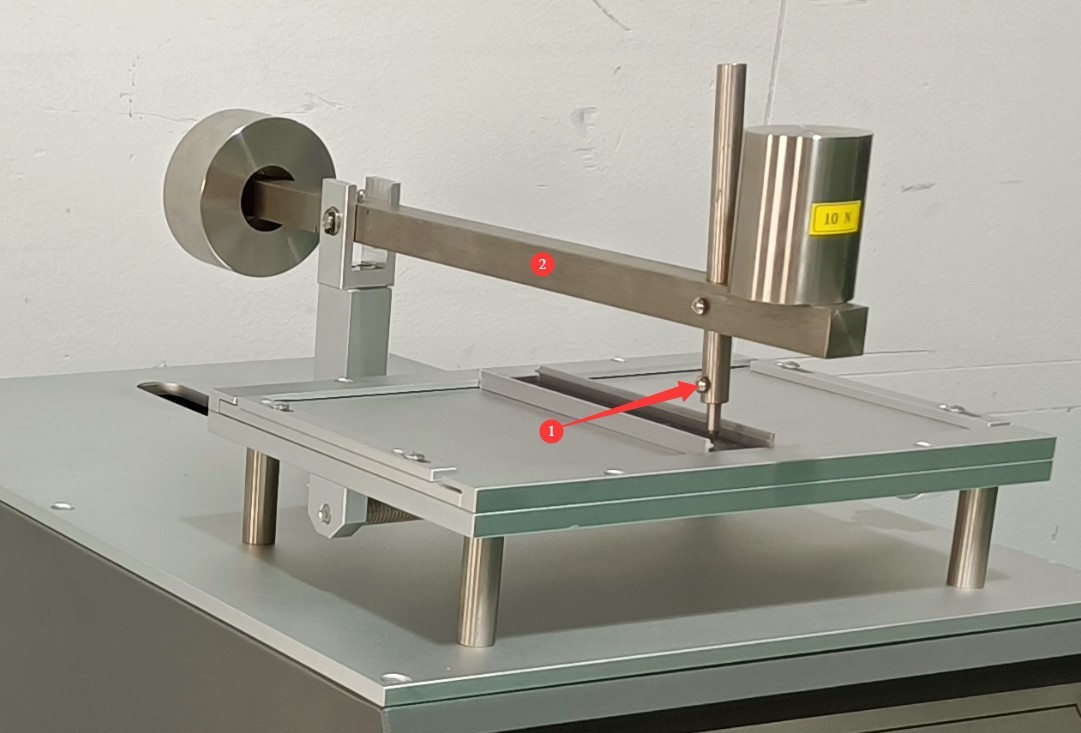
Рисунок 3
Next, adjust the position of the counterweight so that the steel needle is in balance. Finally, reinstall the weights, ensuring they are securely fastened and do not wobble.
3.4 Включение оборудования
Verify that the power cord is properly connected, turn on the circuit breaker on the side of the device, and then press the green power button on the front of the device. The touchscreen will display the operating interface. If any abnormalities occur, refer to Chapter 7 for troubleshooting.
4. Operating the Touchscreen Program for The Coating Scratch Resistance Test Device
4.1 Введение в сенсорный интерфейс
4.1.1 Основной интерфейс
① Ruler, in mm; the black crosshair indicates the current position of the steel needle; ② Start or stop the test; ③ Reset: Sets the current position of the steel needle to the starting position (near the front end); during testing, the steel needle is pulled backward; ④ Current position of the steel needle; ⑤ Number of tests performed;⑥ Counting mode: Select “x1” to count one round trip as one count; select “x2” to count two round trips as one count; ⑦ Reset to 0: Tap to return the steel needle to its initial position; ⑧ Forward: Tap to move the steel needle forward; ⑨ Backward: Tap to move the steel needle backward.⑩ Settings: Tap to enter the parameter settings screen.
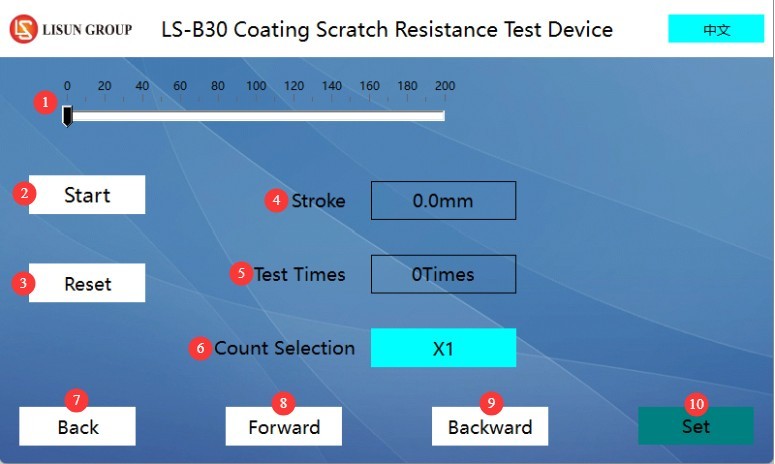
Рисунок 4
4.1.2 Интерфейс настройки параметров
① Test count setting: Set to 1 according to the standard; ② Test speed setting; ③ Manual control of steel needle speed setting; ④ Scratch displacement setting.
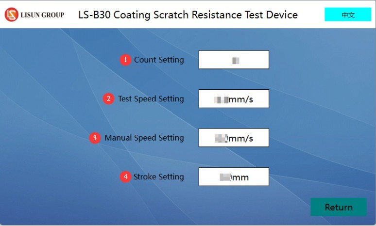
Рисунок 5
4.2 Процедура испытаний
In accordance with Appendix G.13.6.2 and G.4 of the GB/T 4943.1-2022 standard (IEC 62368-1:2018 G.13.6.2 and G.4), the following examples illustrate how to conduct the tests. Customers may configure parameters other than those shown in the examples based on their specific requirements:
The number of tests was set to 1; the test speed and the manually controlled steel needle speed were both set to 20 mm/s; and the scratch displacement was set to 50 mm.
Return to the main screen and select “x2” as the counting mode. Lift the steel needle, tap “Forward” or “Back” to move the needle to the appropriate position, and then tap “Reset” to set the current position as the starting point. Move the sample stage or the sample to position it correctly, and then lower the steel needle so that it comes into contact with the sample.
Click “Start” to begin the test. The steel needle moves backward, and the test stops after covering a distance of 50 mm.
Raise the steel needle and click “Reset to 0” to return the needle to its initial position. Then move the sample holder or the sample to prepare for the next test. Leave a space of at least 5 mm between each pair of parallel scratches.
After completing the test in this direction, rotate the sample 90 degrees and continue with the same test. Be sure that the scratches in the two directions do not intersect.
4.3 Мониторинг процесса тестирования
During the test, observe whether the displacement and cycle count displayed on the touchscreen are normal, and check for any unusual noises or stuttering during equipment operation.
If any abnormalities are detected, stop the test immediately, troubleshoot the issue, and then restart the test.
5. Процедуры после испытаний
5.1 Recording of Test Data
Equipment Parameters: Number of tests, scratch speed, displacement, force applied, and test count mode.
Sample Information: Sample Name, Specifications, Production Batch, Test Location.
Test Results: Number of scratches, spacing between scratches, whether all five pairs of conductive parts were scratched, and whether the sample coating was punctured or damaged.
5.2 Извлечение и обработка образцов
Handle the sample with care when removing it, taking care not to touch the scratched area. Inspect the sample; after testing, the coating must not have come loose or been punctured.
If further testing of the sample is required, it may be subjected to the dielectric strength test specified in Clause 5.4.9.1 of GB/T 4943.1-2022 (Clause 5.4.9.1 of IEC 62368-1:2018) between conductors, in accordance with relevant standards.
НИКОГДА не выключаться
Once you have confirmed that the device has returned to its normal state, turn off the device’s power switch and unplug the power cord.
6. Ежедневное техническое обслуживание и уход за оборудованием.
6.1 Ежедневное обслуживание
6.1.1 Cleaning Tasks
Wipe the surface of the equipment with a dry, soft cloth to remove dust and grease, paying special attention to the touchscreen. Avoid using corrosive cleaning agents.
Clean the surface of the sample holder to remove any remaining sample debris and stains.
6.1.2 Проверка компонентов
Check the tip of the steel needle for wear or deformation, and replace it promptly if any is found.
Check to see if components such as weights, counterweights, and connecting rods are secure and free of looseness.
Test whether the touchscreen buttons are responsive and check for any unusual noises during operation.
6.2 Регулярное обслуживание
6.2.1 Еженедельное обслуживание
Apply a small amount of lubricant (use a specialized mechanical lubricant) to the moving parts of the sample holder, such as the guide rails and the steel-pin drive mechanism, to ensure smooth movement.
Check the power cord and plug for signs of aging or damage, and ensure that the connections are secure.
6.2.2-месячное обслуживание
Remove the steel needle for a thorough inspection. If the tip is severely worn or the fillet radius exceeds the range of 0.25 ± 0.02 mm, replace it with a new steel needle.
Calibrating the axial force of the steel pin: Use a force gauge to measure the applied force. If the force deviates from 10 N ± 0.5 N, calibrate by adjusting the counterweight or replacing the weights.
Check the internal circuit connections for loose wires and clean out any dust from the electrical box (be sure to turn off the power before doing so).
6.3 Долгосрочное хранение и обслуживание
6.3.1 Preparation Before Storage
When the equipment is not in use for an extended period, it must be cleaned and reset; the weights and steel pins must be removed, and the equipment must be stored in separate packaging.
Turn off the power, unplug the power cord, and neatly coil and store the power cord.
6.3.2 Требования к условиям хранения
Place the equipment in a dry, well-ventilated environment free of corrosive gases, and avoid direct sunlight and damp conditions.
Place a moisture-proof mat under the equipment and cover it with a dust cover to prevent dust and moisture from entering.
7. Поиск и устранение распространенных проблем
7.1 Электрические неисправности
7.1.1 нет питания
Possible causes: The power cord is not plugged in securely, the power outlet is faulty, or the device’s power switch is broken.
Solution: Unplug and replug the power cord, and check if the outlet is live; if the switch is damaged, contact a professional to replace it.
7.1.2 Сенсорный экран не реагирует
Possible causes: Loose touchscreen flex cable, internal circuit failure, or the device has not fully booted up.
Solution: Turn off the power, wait 5 minutes, and then restart the device; if it still does not respond, contact the supplier to have the circuit or touchscreen repaired.
7.2 Механические неисправности
7.2.1 Steel Pin Jam
Possible causes: Improper installation of the steel pin, a jam in the drive mechanism, or insufficient lubrication in the guide rail.
Solution: Remove and reinstall the steel pin; remove any foreign objects from the drive mechanism; apply lubricant to the guide rail.
7.2.2 Abnormal Movement of the Sample Holder
Possible causes: Loose mounting bolts on the support platform, wear on the moving mechanism, or an unbalanced sample placement.
Solution: Tighten the mounting bolts; inspect the moving mechanism for wear and replace parts as necessary; reposition the sample to ensure it is balanced and securely fastened.
7.3 Abnormal Test Data
7.3.1 Inaccurate Application of Force
Possible causes: deviations in the weight of the calibration weights, improper adjustment of the counterweights, or wear on the steel pins.
Solution: Replace the standard 10N weight; readjust the balance; inspect the steel needle and replace it if necessary.
7.3.2 Unstable Scratch Speed
Possible causes: Incorrect speed parameter settings, drive mechanism failure, or power supply voltage fluctuations.
Solution: Recalibrate the speed parameters; inspect and repair the drive mechanism; ensure a stable power supply voltage (a voltage regulator may be used).