
 Английский
 中文简体
中文简体 Русский
 Español
 Português
 Türkçe
 العربية
 Deutsch
 Polski
 Italiano
 Français
 한국어
한국어 ไทย
ไทย Tiếng Việt
 日本語
日本語





























Симулятор смещения опорной точки и источника питания
Руководство пользователя
Применимый LISUN models: LIS-OFFSET-10V10A
1. Базовое понимание оборудования
1.1 Обзор продукта
The LIS-OFFSET-10V10A Ground Reference and Supply Offset Simulator employs a four-quadrant bipolar power supply architecture with constant-voltage/constant-current dual modes, with a maximum output of ±10V/±10A and a bandwidth of 100 kHz. It is specifically designed for ground reference and power supply offset testing in automotive electronics, simulating potential difference conditions where multiple power supplies and ground paths coexist in a vehicle, and verifying the operational reliability of in-vehicle ECUs and components under potential offset conditions.
1.2 Применимые стандарты
| Стандарт Номер регистрации | Стандарт Название |
|---|---|
| GB/T 28046.2-2019, пункт 4.8 | Environmental Conditions and Tests for Electrical and Electronic Equipment in Road Vehicles—Part 2: Electrical Loads |
| ISO 16750-2:2023, Clause 4.8 | Дорожные транспортные средства — Условия окружающей среды и испытания электрического и электронного оборудования — Часть 2: Электрические нагрузки |
| Ford EMC-CS-2009.1, Clause 18.0 | Electromagnetic Compatibility Specification for Automotive Electrical and Electronic Components |
| BMW GS 95024 Раздел 5.1 | Электрические и электронные компоненты в автомобилях – требования и испытания. |
| Nissan 28400 | Технические условия испытаний автомобильных электрических и электронных компонентов |
| FMC1278 CI 210 | Automotive Electrical and Electronic Test Standard |
2. Меры предосторожности при использовании
2.1 Требования к окружающей среде
Температура окружающей среды: 23 °C ± 5 °C; относительная влажность: 45–75%, без конденсации; высота над уровнем моря: ≤2000 м; отсутствие сильных вибраций или электромагнитных помех в окружающей среде; использование оборудования в пыльных, легковоспламеняющихся или взрывоопасных средах строго запрещено.
2.2 Требования к источнику питания
Input power supply: AC 220 V ±10%, 50 Hz; Input power: ≤1 kW; The power supply must be reliably grounded, with a grounding resistance of ≤4 Ω; It is recommended to use a voltage-stabilized power supply to prevent power grid fluctuations from affecting test accuracy.
2.3 Принципы электропроводки
Use power cables with the specified wire gauge to prevent overheating under high current conditions; keep test cables as short as possible and route them in parallel to minimize the impact of parasitic parameters; route signal and power cables separately to avoid cross-interference.
2.4 Правила техники безопасности при эксплуатации
Wear insulated protective gear; before testing, ensure that all connections are secure and that there are no exposed conductors; Do not connect or disconnect test cables during testing to avoid arc burns; do not touch the DUT, test fixtures, or output terminals while the output is active to prevent the risk of electric shock from potential differences; if you hear unusual noises, smell an odor, or see smoke, immediately disconnect the power; during prolonged continuous testing, ensure the equipment is properly ventilated for heat dissipation.
2.5 Precautions for the Device Under Test (DUT)
All input and output ports of the DUT must be connected to representative analog vehicle loads and networks to simulate real-world vehicle operating conditions; the DUT must be configured in operating mode 3.4 as specified in ISO 16750-1, and its functional status must be monitored throughout the test; When multiple internal ground pins of the DUT are internally connected, the offset voltage must be applied simultaneously to all connected ground pins.
3. Обзор оборудования
3.1 Передняя панель
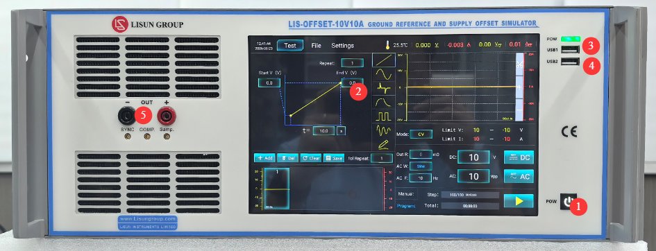
См. Рисунок 3-1.
| Номер регистрации | Внимание |
|---|---|
| ① | Device Power Switch: Press briefly to turn on; press and hold to turn off. |
| ② | 10.1-дюймовый емкостный сенсорный экран |
| ③ | Порт USB1: Используется LISUN инженерам для отладки устройств; пользователям он не нужен. |
| ④ | Порт USB 2.0, который можно использовать для подключения мыши для управления сенсорным экраном или для подключения USB-накопителя для обновления программного обеспечения или файлов базы данных. |
| ⑤ | Output connector—pay attention to polarity |
3.2 Задняя Панель
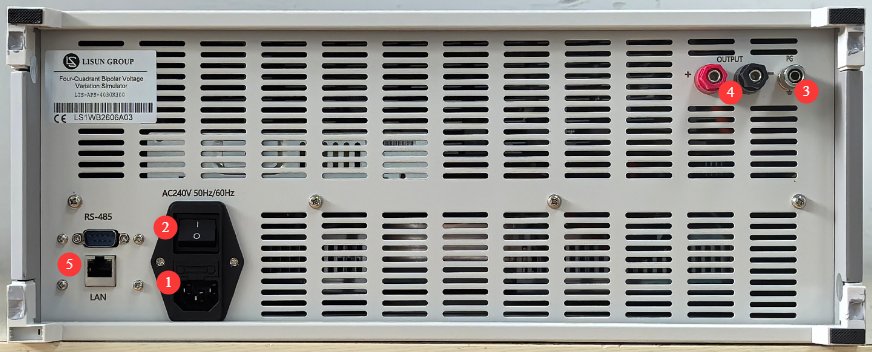
См. Рисунок 3-2.
| Номер регистрации | Внимание |
|---|---|
| ① | Разъем для сетевого шнура и предохранитель; убедитесь, что источник питания надежно заземлен. |
| ② | Автоматический выключатель, главный выключатель питания для оборудования. |
| ③ | Protective ground terminal: If the input power supply does not have a reliable ground connection, this terminal must be connected separately to ground. |
| ④ | Output jacks—pay attention to polarity; these function the same as the front-panel output jacks. |
| ⑤ | RS485 port/LAN port, which can be connected to a computer to use the host software (for backup purposes). The host software offers the same functionality as the touchscreen; please contact us if needed. |
4. Введение в программу сенсорного экрана
This device is essentially a four-quadrant bipolar power supply. For information on using the four-quadrant bipolar power supply program, please refer to the LIS-APS Operating Instructions. These instructions cover only the operations required when using the device as a Ground Reference and Supply Offset Simulator.
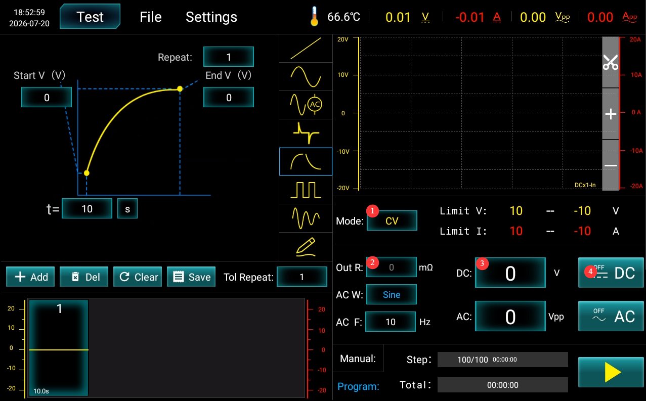
См. Рисунок 4-1.
| Номер регистрации | Внимание |
|---|---|
| ① | Set to CV (Constant Voltage) |
| ② | Output impedance is set to 0 |
| ③ | Set the offset voltage |
| ④ | Click to enable/disable the offset voltage output |
5. Ground Reference and Power Supply Offset Test
5.1 Verification of Test Conditions
Verify the DUT specifications: Confirm whether it is a 12V or 24V system; Verify the number and pin definitions of the DUT’s power and ground pins;
verify the auxiliary power supply: an external base power supply (typically 13.5 V for 12 V systems and 28 V for 24 V systems);
Verify the DUT load: Connect the DUT inputs and outputs to corresponding simulated loads to simulate the actual vehicle wiring harness network;
Verify test standard requirements: Confirm the hold time for each test condition, the operating mode required for the DUT, and the criteria for passing the test.
5.2 Аппаратная проводка
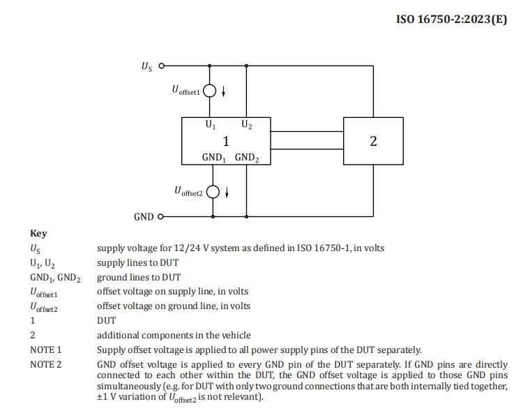
See Figure 5-1 for the standard wiring diagram (taken from ISO-16750 2:2023, Figure 18).
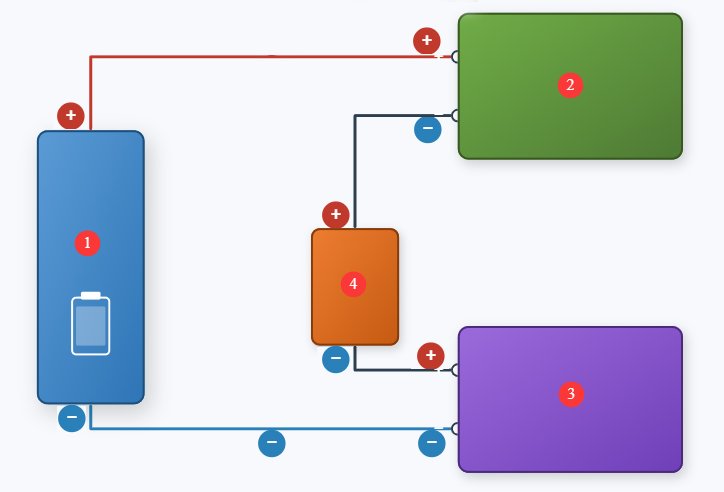
The LIS-OFFSET-10V10A is a single-channel device that must be used in conjunction with your LIS-AP device. Refer to Figure 5-2 for the wiring diagram; be sure to observe the polarity indicated in the diagram when making connections.
| Номер регистрации | Внимание |
|---|---|
| ① | Вспомогательный источник питания |
| ②③ | LIS-OFFSET and LIS-AP have the same function and are used to simulate power supply offset and ground offset. ② is used to simulate the power supply offset Uoffset1, and ③ is used to simulate the ground (GND) offset Uoffset2. |
| ④ | DUT |
5.3 Explanation of the Standard Test Matrix for ISO 16750-2-2023
The table below lists the eight test conditions specified in the standard; typically, each condition must be maintained for 30 to 60 seconds to observe the DUT’s operating status.
| Test Conditions: Case | Power Supply Offset DC Output (Uoffset1) | Ground Offset DC Output (Uoffset2) | Описание теста |
|---|---|---|---|
| Кейс 1 | 0 V | 1V | 1 V GND offset, no power supply offset |
| Кейс 2 | 1V | 1V | 1 V GND offset, +1 V supply offset |
| Кейс 3 | -1V | 1V | 1 V GND offset, –1 V supply offset |
| Кейс 4 | 0 V | -1V | ‑1V GND offset, no power supply offset |
| Кейс 5 | 1V | -1V | ‑1V GND offset, +1V power supply offset |
| Кейс 6 | -1V | -1V | -1V GND offset, -1V power supply offset |
| Кейс 7 | 1V | 0 V | No GND offset, +1V supply offset |
| Кейс 8 | -1V | 0 V | No GND offset, -1V supply offset |
When the DUT has multiple independent power supply pins and multiple independent ground pins, each Набор power-ground loops must undergo a complete repetition of all 8 test cases; if multiple GND pins within the DUT are internally interconnected, the offset voltage must be applied simultaneously to all interconnected ground pins; All input and output load networks must match those of the actual vehicle; no no-load testing is permitted.
5.4 Оценка результатов испытаний
| Уровень | Definition of Standards |
|---|---|
| Класс A | During and after testing, all functions met the design specifications; there were no abnormalities and no out-of-tolerance conditions. |
| Класс B | Functioned normally during testing, with only brief instances of parameters exceeding tolerance limits; automatic recovery from stress relief; storage function must be Grade A. |
| Класс C | The test procedure allows for functional failures; normal operation is automatically restored after the offset voltage is removed. |
| Класс D | Failed during testing; after the stress is removed, manual reset or a power cycle is required to restore operation. |
| Класс Е | Permanent damage; hardware needs to be repaired or replaced |
Note: Clause 4.8 of ISO 16750-2:2023 does not itself specify which class the DUT must meet, but this test typically mandates Class A.
6. Ежедневное техническое обслуживание и уход за оборудованием.
6.1 Ежедневная уборка
6.1.1 График и порядок уборки
После каждого использованияОчистите поверхность сенсорного экрана и удалите пыль с панели устройства;
Еженедельные: Clean the equipment housing and vent filters;
Ежемесячно: Очистка оборудования от пыли (выполняется специалистом).
6.1.2 Методы очистки
Wipe the exterior with a clean, soft, lint-free cloth; use a dedicated screen cleaner for the touchscreen; clean the vents with a soft-bristled brush and a vacuum cleaner if necessary; do not use corrosive solvents such as acetone.
6.2 Периодические проверки
Проверьте шнур питания на наличие повреждений или износа; убедитесь в надежности заземления; проверьте нормальную работу вентилятора; проверьте чувствительность кнопок и сенсорного экрана; проверьте клеммные колодки на наличие окисления или ослабленных соединений.
6.3 Хранение и обработка
6.3.1 Требования к долговременному хранению
Storage Conditions: Temperature -10°C to +50°C, humidity ≤85%; Clean the equipment and apply dust protection before storage; Power on the equipment once every 3 months, running it for at least 30 minutes each time; Avoid stacking or applying heavy pressure to prevent the panel from warping.
6.3.2 Меры предосторожности при обращении
Перед перемещением устройства отключите все внешние кабели; используйте оригинальную упаковку и убедитесь, что она должным образом защищена и амортизирована; во время транспортировки устройство должно находиться в вертикальном положении, избегайте сильной тряски; при подъеме держитесь за нижнюю и боковые части устройства — не поднимайте его за панель.
6.4 Требования к интервалу калибровки
To ensure the measurement accuracy and operational reliability of the equipment, it is recommended that it be sent periodically to a qualified third-party metrology laboratory for calibration. The recommended calibration interval is 12 months. The specific calibration interval may be determined by the user based on frequency of use, environmental conditions, and quality system requirements.
7. Поиск и устранение распространенных проблем
| Признаки неисправности | Возможные причины | Метод |
|---|---|---|
| Устройство не включается | Главный выключатель питания на задней панели не включен, или перегорел предохранитель. | Включите выключатель питания, расположенный на разъеме для шнура питания на задней панели устройства; проверьте предохранитель, и если он перегорел, замените его предохранителем того же номинала. |
| Неисправность сенсорного экрана после включения питания | Система зависла, ослаблен шлейф. | If the problem persists after restarting, disconnect the power, open the device’s casing, and check whether the touchscreen ribbon cable is loose. |
| Test Stopped Automatically Midway | Over-temperature protection triggered; overcurrent/overvoltage protection triggered | Check whether the equipment’s ventilation is obstructed and whether the ambient temperature is too high; check the DUT for short circuits or overloads. |
| USB Flash Drive Not Recognized | USB drive format is incompatible or has too much storage capacity | Используйте USB-накопитель, отформатированный в FAT32, емкостью не более 32 ГБ; если это не поможет, попробуйте другой USB-накопитель. |
| No voltage/current after output is enabled | DUT Wiring Abnormality, Protection Function Triggered | After disconnecting the output, verify that the DUT is wired correctly and that there are no open circuits or short circuits; check for any overvoltage, overcurrent, or overtemperature warnings, and retry after resolving the issue. |
| Abnormal Output Voltage/Current Accuracy | Improper output resistance settings; long-term lack of calibration | Verify that the source impedance parameters meet the test requirements; contact a third-party metrology organization to perform calibration. |