
 Английский
 中文简体
中文简体 Русский
 Español
 Português
 Türkçe
 العربية
 Deutsch
 Polski
 Italiano
 Français
 한국어
한국어 ไทย
ไทย Tiếng Việt
 日本語
日本語





























Симулятор обрыва/короткого замыкания автомобильного жгута проводов
Руководство пользователя
Применимый LISUN models: LIS-LSCS-1730、LIS-LSCS-1750
1. Базовое понимание оборудования
1.1 Классификация моделей
| LISUN Модель | LIS-LSCS-1730 | LIS-LSCS-1750 |
|---|---|---|
| Количество переключателей | Маршрут 30 | Маршрут 50 |
| Максимальное напряжение | 60 В постоянного тока/220 В переменного тока | |
| Максимальный ток | 10 A per channel, 50 A maximum for the entire unit | |
| On/Off Switches (S1) | <20 mΩ/10 A | |
| Short-Circuit Switches (S2/S3) | <20 mΩ/10 A | |
| Power Switches (S4/S5) | <5 mΩ/50 A | |
| Open-Circuit/Short-Circuit Trip Time | 20 мс–10000 с | |
| Количество циклов | 1 – 10000 раз | |
| Number of Test Steps | Шаги 1–255 | |
| Конфигурация функции | Full touchscreen, built-in standard library, voltage and current monitoring | |
| Система управления | 10.1-inch Android Capacitive Touchscreen Display with Chinese and English Support | |
| Условия эксплуатации | Temperature: 10–40°C; Humidity: 30%–70% | |
| Габаритные размеры: | 460 × × 180 550 мм | |
| Вес | О 8 кг | |
1.2 Compliance with Reference Standards
This equipment’s testing capabilities fully cover the requirements of the following international standards, national standards, and corporate standards of major automakers, and can be used directly for compliance testing under the corresponding provisions.
1.2.1 Международные и национальные стандарты
| Standard Number and Section | Стандартное название | Corresponding Test Items |
|---|---|---|
| GB/T 45120-2024, пункт 10.15 | Road Vehicles—Electrical Requirements and Tests for 48-V Power Supplies: Short Circuits in Signal Lines and Load Circuits | 48V System Signal Line/Load Circuit Short-Circuit Test |
| GB/T 28046.2-2011, Clauses 4.9 and 4.10 | Environmental Conditions and Tests for Electrical and Electronic Equipment in Road Vehicles—Part 2: Electrical Loads | Open-Circuit Test / Short-Circuit Protection Test |
| ISO 16750-2:2023, Clauses 4.9 and 4.10 | Road Vehicles—Environmental Conditions and Testing for Electrical and Electronic Equipment—Part 2: Electrical Loads | Open-Circuit Test / Short-Circuit and Overload Protection Test |
1.2.2 Corporate Standards of Major Automakers
| Standard Number and Section | Стандартное название | Corresponding Test Items |
|---|---|---|
| JA 3700-MH-4-2021/2025, Section 4.20 | FAW Group Passenger Vehicle Electronic and Electrical Components: Electrical Environmental Specifications | Тест на короткое замыкание |
| QLP YSY 0231-2024, Section 16.17 | Zhejiang Leapmotor Technology Co., Ltd. Corporate Standards | Short-Circuit Protection Testing for Signal Lines and Load Circuits |
| QSK J07.362-2024, Sections 5.17/5.20 | Electrical Test Methods for Saelis Electrical and Electronic Components and Subsystems | Connector Disconnection Test / Short-Circuit Test of Signal and Load Circuits |
| SMTC 3 800 001, Section 5.16 | SAIC Group General Testing Requirements for Electronic and Electrical Components | Short-Circuit Protection Testing for Signal Lines and Driver Circuits |
| VW 80000:2021/2022 E-17/E-20 | Test Specifications for Electrical Units in Vehicles Weighing Up to 3.5 metric tons | Signal and Load Circuit Short-Circuit Test / Reverse Power Feed-Through Test |
| VDS 28401-02 [4]:2025, Section 6.1.5 | Dongfeng Nissan General EMC Test Standard for E& E Components on the Test Bench: EQ/TE05 | Input/Output Port Short-Circuit Test to Power and Ground |
1.3 Сценарии приложений
The LIS-LSCS Series Automotive Wire Harness Open‑Short Simulator is a specialized testing device designed for automotive electronic and electrical testing and R& D. It can simulate standard test conditions—such as open circuits, short circuits, short circuits to the power supply, short circuits to ground, and connector disconnections—on signal lines and load circuits, meeting the stringent testing requirements for wiring harness reliability and protection performance set forth by GB national standards, ISO international standards, as well as the stringent testing requirements of major automakers regarding wiring reliability and protection performance. The equipment supports independent or synchronized control of multiple channels, allowing all tests to be completed with a single wiring setup, which significantly simplifies manual operations and improves testing efficiency and consistency.
1.3.1 Применимые отрасли и сценарии
Automotive OEMs: DV/PV validation of components, incoming quality sampling inspections, and electrical reliability testing; Automotive parts manufacturers: Factory-level reliability testing of wiring harnesses, controllers, and sensors; Third-party testing organizations: Automotive electronics compliance certification and standards conformity testing; Research and education: R& D in automotive electronics technology, as well as teaching and experimental demonstrations.
1.3.2 Испытуемые
Complete low-voltage wiring harness assemblies and local wiring harness subsystems; input and output ports for various automotive controllers (BCM, ECU, VCU, BMS, etc.); wiring harnesses for in-vehicle sensors and actuators; and wiring harnesses for external components such as body electronics and in-vehicle entertainment systems.
2. Меры предосторожности при использовании
2.1 Требования к окружающей среде
Ambient temperature: 23 °C ± 5 °C; relative humidity: 45–75%, non-condensing; altitude: ≤2000 m; no strong vibrations or electromagnetic interference in the vicinity; the equipment must not be used in dusty or flammable and explosive environments.
2.2 Требования к источнику питания
Input power supply: AC 220 V ±10%, 50 Hz; Input power: ≤1 kW; The power supply must be properly grounded, with a grounding resistance of ≤1 Ω; It is recommended to use a voltage regulator to prevent power grid fluctuations from affecting test accuracy.
2.3 Принципы электропроводки
Use power cables with the specified wire gauge to prevent overheating under high current conditions; keep test cables as short as possible and route them in parallel to minimize the impact of parasitic parameters; ensure that the DUT (Device Under Test) enclosure is reliably connected to the equipment’s protective ground; and route signal and power cables separately to avoid cross-interference.
2.4 Правила техники безопасности при эксплуатации
Wear appropriate insulated protective gear; before testing, ensure that all connections are secure and that there are no exposed conductors; do not touch or connect/disconnect wiring harnesses or cables during testing; if you hear unusual noises, smell an unusual odor, or notice smoke, disconnect the power immediately; when conducting prolonged continuous testing, ensure adequate ventilation and heat dissipation for the equipment.
3. Обзор оборудования и схема подключения
3.1 Передняя панель
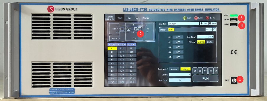
См. Рисунок 3-1.
| Номер регистрации | Внимание |
|---|---|
| ① | Device power Switches: Press briefly to turn on, press and hold to turn off. |
| ② | 10.1-дюймовый емкостный сенсорный экран |
| ③ | Порт USB1: Используется LISUN engineers for device debugging; users do not need to use it |
| ④ | Порт USB 2.0, который можно использовать для подключения мыши для управления сенсорным экраном или для подключения USB-накопителя для обновления программного обеспечения или файлов базы данных. |
3.2 Задняя Панель
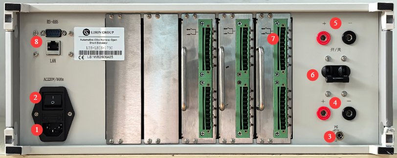
См. Рисунок 3-2.
| Номер регистрации | Внимание |
|---|---|
| ① | Разъем для сетевого шнура и предохранитель; убедитесь, что источник питания надежно заземлен. |
| ② | Автоматический выключатель, главный выключатель питания для оборудования. |
| ③ | Клемма защитного заземления: Если источник входного питания не имеет надежного заземления, эту клемму необходимо подключить к заземлению отдельно. |
| ④ | Разъем питания тестируемого устройства: Для тестируемого устройства необходимо обеспечить подходящий внешний источник питания. Вы можете использовать LISUNИспользуйте четырехквадрантный источник питания серии LIS-APS или другой подходящий стабилизированный источник постоянного тока, соответствующий тестируемому устройству. Обратите внимание на полярность. |
| ⑤ | DUT power output connector; connect the DUT power cord here. Observe the polarity. |
| ⑥ | DUT Power Switches |
| ⑦ | Signal wire harnesses for continuity, short circuit, and connection testing; 30/50 channels total |
| ⑧ | Интерфейс RS485/порт LAN, который можно подключить к компьютеру для использования программного обеспечения (в целях резервного копирования). Программное обеспечение предоставляет те же функции, что и сенсорный экран; при необходимости свяжитесь с нами. |
3.3 Введение в аксессуары
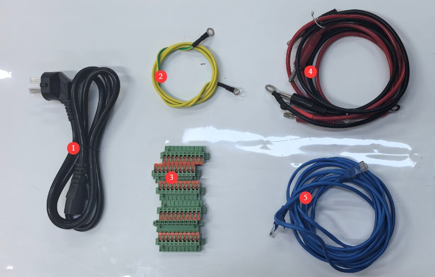
См. Рисунок 3-3.
| Номер регистрации | Внимание |
|---|---|
| ① | Шнур питания |
| ② | Провод заземления |
| ③ | Модуль подключения сигнальной линии |
| ④ | DUT Power Supply Input and Output Cables |
| ⑤ | Ethernet-кабель, используемый для подключения компьютера к программному обеспечению. |
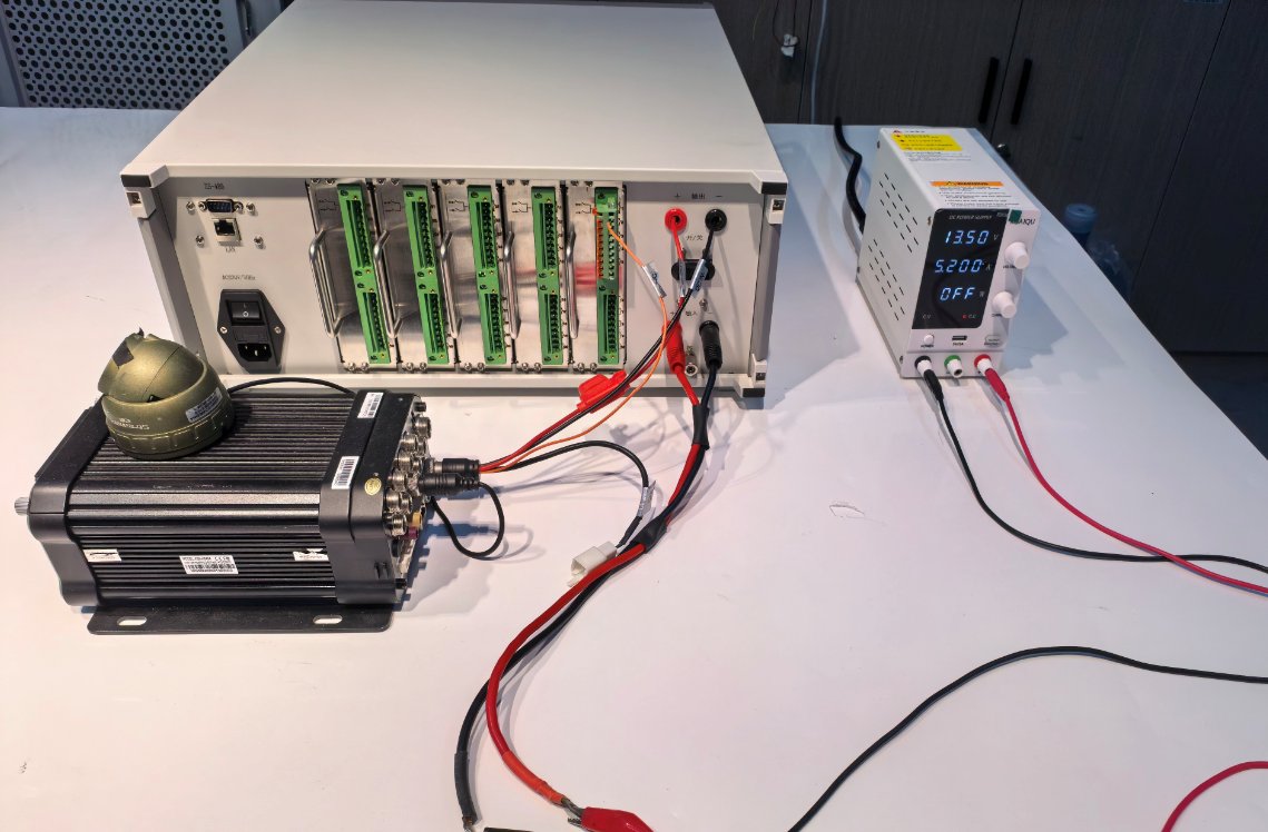
See Figures 3-4 for a schematic diagram of the external power supply and DUT connections:
See Figures 3-4 for a schematic diagram of the external power supply and DUT connections:
4. Введение в программу сенсорного экрана
4.1 Тестовый интерфейс
См. Рисунок 4-1.
| Номер регистрации | Внимание |
|---|---|
| ① | Equipment Main Circuit Schematic |
| ② | Выберите канал, который хотите протестировать. |
| ③ | Нажмите, чтобы запустить встроенные стандартные тесты устройства, или выберите пользовательский тест. |
| ④ | Если вы выберете встроенные стандарты устройства, все параметры тестирования в областях, выделенных красной рамкой, уже будут настроены в соответствии с соответствующими стандартами и не требуют изменения; если вы выберете «Пользовательский тест», вы сможете изменить параметры тестирования. |
| ⑤ | For custom tests, you can save the configured test parameters to the device so they can be recalled later. |
| ⑥ | Время выполнения отображается и рассчитывается автоматически; после начала теста появится индикатор выполнения, показывающий ход теста. |
| ⑦ | Switches for S1 through S5 have already been configured in the test parameters. However, if you need certain Switches to remain normally open during the test, you can manually click to close Switches corresponding switch before the test begins, ensuring it remains in the normally open state throughout the test. |
| ⑧ | ЗАПУСК: После выбора формы сигнала и других параметров нажмите эту кнопку, чтобы начать тест. Во время теста индикатор выполнения обновляется раз в секунду, показывая текущий прогресс, пока тест не будет завершен. Нажмите эту кнопку еще раз во время теста, чтобы остановить текущий тест. |
| ⑨ | Display the DUT’s current voltage and current |
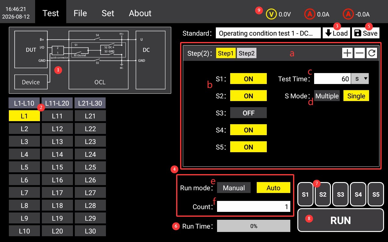
Test Parameter Overview: a) Add, delete, or reset test steps; Switches Switch status settings; c) Test duration; Switches: simultaneous or individual; e) Run mode: manual or automatic (in automatic mode, the system automatically proceeds to the next test step once the current one is completed); f) Number of cycles.
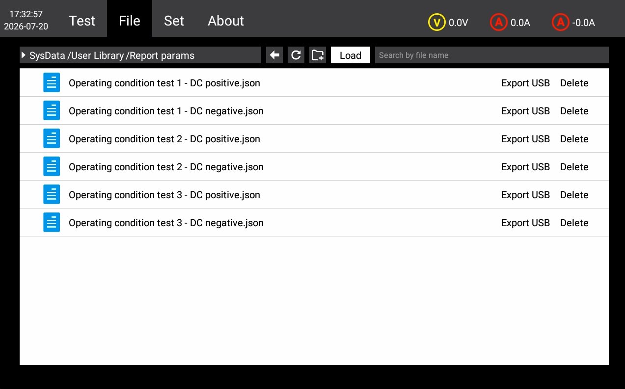
4.2 Интерфейс файлов базы данных
См. Рисунок 4-2.
| Номер регистрации | Внимание |
|---|---|
| ① | Test Plan Standard Library Management. You can manage the custom test parameters you have saved; please do not modify or delete the test parameters built into the device. |
| ② | If you have other standard tests but do not wish to create custom tests, please contact us and send us the details of the relevant standards. We will guide you through the process of updating the database file with those standards directly using a USB drive. |
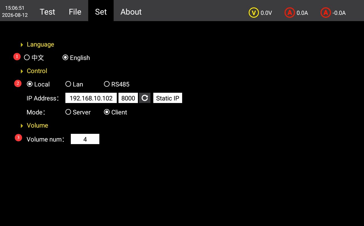
4.3 Интерфейс настроек
См. Рисунок 4-3.
| Номер регистрации | Внимание |
|---|---|
| ① | Переключение между китайским и английским языками |
| ② | Communication settings are set to “LOCAL” by default. If you need to use host computer software, you can switch to the RS485 or LAN port. Please contact us. |
| ③ | Настройки громкости |
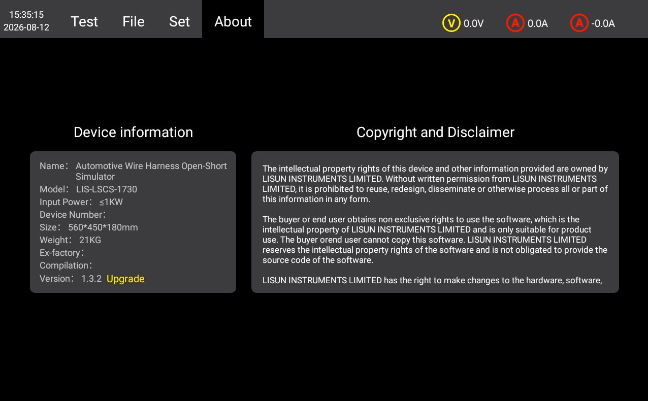
4.4 Об интерфейсе
For device information, firmware version, and copyright notice, see Figure 4-4.
5. Procedures for Conducting Continuity and Short-Circuit Tests on Automotive Wiring Harnesses
5.1 Общие рабочие процедуры
5.1.1 Подключение
Ensure that both the device and the DUT are powered off; use a test cable to connect the device’s DUT power output port to the DUT’s power cord; Use a cable to connect an external power supply (LIS-APS or other regulated DC power supply) to the DUT input power supply connector on the rear panel of the device; connect the DUT signal cables to the signal cable channels on the rear panel of the device using the dedicated terminals.
5.1.2 Настройки параметров
Set the test parameters as described in Section 4.1, and select the channels you want to test.
5.1.3 Этапы выполнения теста
Turn on the external power supply and connect it to the DUT; turn Switches on the back of the device and verify that the DUT is operating normally; on the touchscreen test interface, click the RUN button to start the test; observe the DUT’s operating status and record any observations; wait for the test to complete; in case of an emergency, you may press the stop button to halt the test immediately.
5.2 Typical Standard Test Conditions and Criteria for Acceptance
5.2.1 Open-Circuit Test (Corresponding to GB/T 28046.2, Section 4.9 / ISO 16750-2, Section 4.9)
Цель теста: To verify the DUT’s functional behavior under open-circuit faults in signal and load lines, as well as its ability to recover after the fault is cleared.
Критерии «пройден/не пройден»: Grade A: All functions operate completely normally during and after testing, with no performance degradation; Grade B: Acceptable temporary degradation occurs during testing; functionality automatically recovers after the fault is resolved; Grade C: Functionality fails during testing but can be restored through manual reset or reboot, with no hardware damage; Grade D: Permanent hardware damage occurs and functionality cannot be restored; the unit is deemed to have failed the test.
The specific qualification levels are subject to the product’s technical specifications; key functions typically require a Grade B or higher.
5.2.2 Short-Circuit Protection Test (Corresponding to GB/T 28046.2, Clause 4.10 / ISO 16750-2, Clause 4.10)
Цель теста: To verify the DUT’s ability to protect against short circuits between its ports and the positive power supply terminal or ground, ensuring there is no permanent damage or safety risk.
Критерии приема: During testing, the protective mechanism triggered normally, with no smoke, fire, or melting of the housing; after testing, there was no permanent hardware damage, and functionality met the specified grade requirements; the protective device operated as designed, with no secondary failures; and the protective function remained effective upon retesting.
5.2.3 Short-Circuit Test for Signal Lines and Load Circuits in the 48V System (in accordance with GB/T 45120-2024, Clause 10.15)
Цель теста: To verify the short-circuit protection performance of signal lines and load circuits for components in a 48V power supply system.
Требования: A short circuit must not cause safety risks such as fire or loss of control; the protective circuit must operate reliably, and functionality must be restored after the fault is cleared; the low-voltage control section must not be affected by a short circuit and must maintain its basic functionality.
5.2.4 Connector Disconnection Test (in accordance with QSK J07.362-2024, Section 5.17, and other automotive industry standards)
Цель теста: To simulate transient connector contact failures caused by vibration and verify the DUT’s immunity to interference and fault tolerance.
Критерии приема: No system crashes, unexpected resets, or data loss may occur during testing; communication signals must not experience irrecoverable communication interruptions; after testing, all functions must operate normally, with no hidden damage.
5.3 Порядок действий в конце теста
Ensure that both the equipment and the DUT are powered off; disconnect the connections on the DUT side first, then disconnect the connections on the equipment side.
6. Ежедневное техническое обслуживание и уход за оборудованием.
6.1 Ежедневная уборка
6.1.1 График и порядок уборки
После каждого использованияОчистите поверхность сенсорного экрана и удалите пыль с панели устройства;
Еженедельные: Clean the equipment housing and the filters in the vents;
Ежемесячно: Очистка оборудования от пыли (выполняется специалистом).
6.1.2 Методы очистки
Wipe the exterior with a clean, soft, lint-free cloth; use a special screen cleaner for the touchscreen; clean the ventilation openings with a soft-bristled brush and a vacuum cleaner if necessary; do not use corrosive solvents such as acetone.
6.2 Периодические проверки
Check the power cord for damage or wear; check that the ground connection is secure; check that the fan is operating normally; check that the buttons and touchscreen are responsive; check the terminal blocks for oxidation or loose connections.
6.3 Хранение и обработка
6.3.1 Требования к долговременному хранению
Storage Conditions: Temperature -10°C to +50°C, humidity ≤85%; Clean the equipment and apply dust protection before storage; Power on the equipment once every 3 months, running it for at least 30 minutes each time; Avoid stacking or applying heavy pressure to prevent panel deformation.
6.3.2 Меры предосторожности при обращении
Unplug all external cables before moving the device; use the original packaging and ensure it is properly cushioned and protected; keep the device upright during transport and avoid harsh vibrations; when lifting, grip the bottom and both sides of the device—do not lift by the panel.
6.4 Требования к интервалу калибровки
To ensure the measurement accuracy and operational reliability of the equipment, it is recommended that it be sent periodically to a qualified third-party metrology laboratory for calibration. The recommended calibration interval is 12 months. The specific calibration interval may be determined by the user based on frequency of use, environmental conditions, and quality system requirements.
7. Поиск и устранение распространенных проблем
| Признаки неисправности | Возможные причины | Метод |
|---|---|---|
| Устройство не включается | Главный выключатель питания на задней панели не включен, или перегорел предохранитель. | Включите выключатель питания, расположенный на разъеме для шнура питания на задней панели устройства; проверьте предохранитель, и если он перегорел, замените его предохранителем того же номинала. |
| Неисправность сенсорного экрана после включения питания | Система зависла, ослаблен шлейф. | If the problem persists after restarting, disconnect the power, remove the device’s outer casing, and check whether the touchscreen ribbon cable is loose. |
| Тест был автоматически остановлен на полпути. | Over-temperature protection triggered, overcurrent/overvoltage protection triggered, external power interruption | Check whether the equipment’s ventilation is obstructed or whether the ambient temperature is too high; check the DUT for short circuits or overloads; check whether the external power supply has stopped outputting power. |
| USB Flash Drive Not Recognized | Формат USB-накопителя несовместим или его емкость слишком велика. | Use a FAT32-formatted USB drive with a capacity of no more than 32 GB; if that doesn’t work, try a different USB drive. |