
 Английский
 中文简体
中文简体 Русский
 Español
 Português
 Türkçe
 العربية
 Deutsch
 Polski
 Italiano
 Français
 한국어
한국어 ไทย
ไทย Tiếng Việt
 日本語
日本語





























Устройство для испытания на удар маятника
Руководство пользователя
Применимый LISUN модели: IK01-06P
1. Базовое понимание оборудования
1.1 Ключевые параметры
| Параметры | Внимание |
| Combined Mass of Impact Components | 150±1 g and 200±1 g |
| Quality of Mounting Brackets | 10 ± 1 кг |
| Bracket Rotation Angle | ± 60 ° |
| Swing Arm Length | 1000 ± 1 мм |
| Swing Arm Quality | 100 g ± 1 g |
| Material for the swing arm | Steel pipe with an outer diameter of 9 mm and a wall thickness of 0.5 mm |
| Разрешение сенсора | Angle: 0.36 degrees; Height: 0.1 mm |
| Энергия удара | 0.14 Дж, 0.2 Дж, 0.35 Дж, 0.5 Дж, 0.7 Дж, 1 Дж |
Note: According to the requirements of the IEC 60068-2-75 (GB/T 2423.55) standard and the method for calculating equivalent mass, the previous version of the standard used a 150-g impact element, whose equivalent mass was 150 g + (100 g/2) = 200 g; The new standard uses a 200 g impact element, with an equivalent mass of 200 g + (100 g/2) = 250 g. The IK01-06P includes impact elements of both masses.
See Figure 1-1 for the external dimensions.
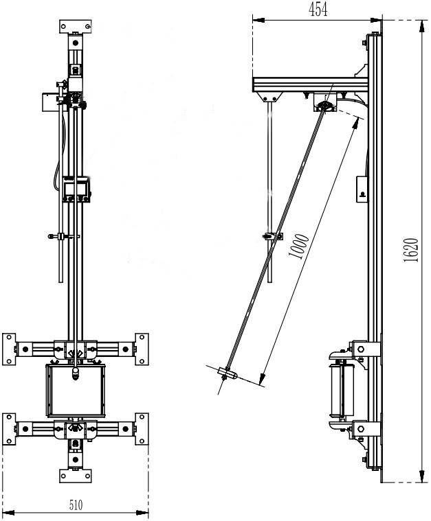
Рисунок 1-1
1.2 Проверка конфигурации оборудования
1.2.1 Распаковка
При распаковке устройства обращайтесь с ним осторожно, чтобы не поцарапать корпус острыми предметами. После распаковки сначала осмотрите внешний вид устройства, чтобы убедиться в отсутствии видимых деформаций или вмятин, а также в том, что кнопки не повреждены и не расшатаны. Если вы обнаружите какие-либо неисправности устройства или его аксессуаров, пожалуйста, немедленно свяжитесь с нами.
1.2.2 Основной блок и принадлежности
Основной блок: 1 IK01-06 Impact Element Impact Test System main unit.
Основные компоненты (рис. 1–2):
| Номер регистрации | Внимание |
| ① | Expansion anchors, used to mount the main unit to a vertical wall |
| ② | USB charging cable, used to charge the display |
| ③ | Spare 150g impact element; the 200g impact element is already installed on the swing arm at the factory. |
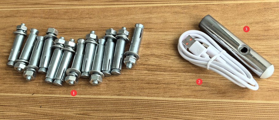
Рисунки 1–2
1.2.3 Загрузка электронных документов
Ссылки для скачивания цифрового руководства пользователя, гарантийного талона и других документов были отправлены нам по электронной почте во время отправки товара. Пожалуйста, скачайте их как можно скорее. Если вы пропустили письмо, вы можете связаться с нами и запросить ссылки для скачивания еще раз.
2. Меры предосторожности.
2.1 Эксплуатационная безопасность
You must wear impact-resistant gloves and safety goggles to prevent flying debris or ricochets from the impact components from causing injury;
Во избежание случайных травм посторонним лицам вход в зону испытаний запрещен.
2.2. Экологическая безопасность
Температуру окружающей среды следует поддерживать в пределах от 5°C до 35°C, а относительную влажность — ≤ 75%.
Leave at least 2000 mm of space in front of the equipment to ensure that the swing arm can lift properly and that there are no obstructions in the surrounding area;
When mounting the equipment on a wall, ensure it is vertical, with a tolerance of ≤0.5°.
3. Обзор оборудования
3.1 Introduction to the Host
Introduction to the Host System Components (Figure 3-1).
| Номер регистрации | Внимание |
| ① | Mounting holes, 12 in total |
| ② | Sample holder, with adjustable angle and position |
| ③ | Impact element, replaceable |
| ④ | Подвеска |
| ⑤ | Регулируемый кронштейн для крепления рычага |
| ⑥ | Fixed Device for the Impact Height of a Swing Arm |
| ⑦ | Display showing the current swing arm angle and impact height |
| ⑧ | Sensor that monitors the angle of the swing arm and automatically calculates the impact height |
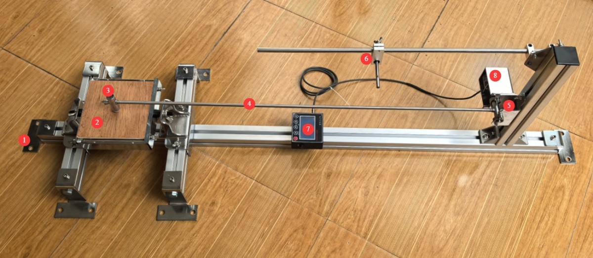
Рисунок 3-1
3.2 Replacing The Impact Element
Steps for Replacing the Impact Element (Fig. 3-2).
| Номер регистрации | Внимание |
| ① | Remove the two small screws at the top and bottom |
| ② | Отвинтить гайку |
| ③ | Unscrew the counterweight, then tap the connecting rod out. |
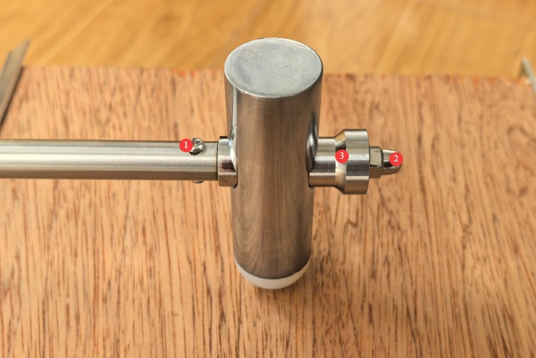
Рисунок 3-2
The disassembled impact components are shown in the figure below (Figure 3-3):
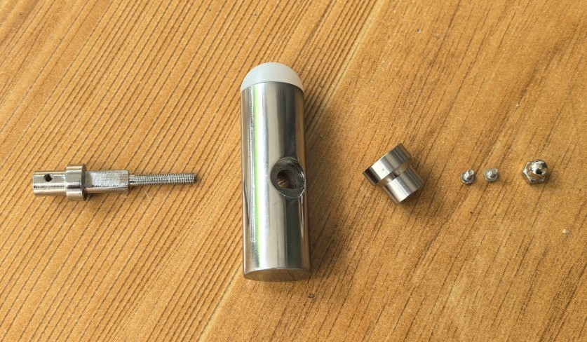
Рисунок 3-3
Next, assemble the impact elements of different weights and install them onto the swing arm, paying attention to the orientation of the hammer head during installation.
3.3 Introduction to the Display
Display Introduction Features (Fig. 3-4).
| Номер регистрации | Внимание |
| ① | USB порт зарядки |
| ② | Display power switch: Press and hold for 1 second to turn on; press briefly to turn off. |
| ③ | Кнопка подтверждения/Кнопка сброса |
| ④ | The adjustment button allows you to set the length of the swing arm; the factory default setting is 1 m. |
| ⑤ | Number Up/Down keys: Increase or decrease the number when setting parameters |
| ⑥ | Battery level indicator—please recharge promptly when the battery is low. |
| ⑦ | Current Impact Height Display |
| ⑧ | Current Swing Arm Angle Display |
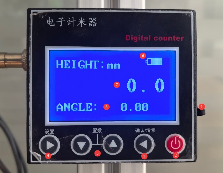
Рисунок 3-4
4. Испытание на удар
4.1 Sample Mounting and Installation
4.1.1 Фиксация образца
Secure the sample in the center of the plywood.
4.1.2 Регулировка положения
The position and angle of the sample holder are adjustable, and the position of the swing arm mounting device is adjustable. Adjust these so that the hammer head and the sample impact point are at the same height, and the direction of impact is perpendicular to the cross-section of the impact point.
4.2 Impact Parameter Settings
4.2.1 Set to 0 at Startup
When you turn on the display, it will show random angle and height values. Press the reset button to set the current swing arm angle and impact height to 0.
4.2.2 Adjusting the Impact Height
Raise the pendulum arm; the display will show its real-time angle and impact height. Refer to the table below to raise the pendulum arm to the desired impact height, and secure it using the pin on the height locking device. See Figure 4-1.
| Уровень ИК | IK01 | IK02 | IK03 | IK04 | IK05 | IK06 | ||||
| Энергия Дж | 0.14 | 0.2 | (0.3) | 0.35 | (0.4) | 0.5 | 0.7 | 1 | ||
| Equivalent mass (kg) | 0.25 | (0.2) | 0.25 | (0.2) | 0.25 | (0.2) | 0.25 | |||
| Высота падения (мм) | 56 | (100) | 80 | (150) | 140 | (200) | (250) | 200 | 280 | 400 |
Note: The values in parentheses correspond to the requirements of the previous version of the standard. If testing is to be conducted in accordance with the previous version of the standard, a 150-gram impact element must be installed.
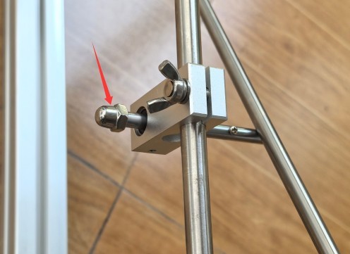
Рисунок 4-1
4.2.3 Испытание на ударную нагрузку IK
Slowly pull out the pin securing the swing arm height (Fig. 4-1) to perform the impact test.
To prevent the impact element from striking repeatedly due to inertia, after the impact element has completed an impact and bounced back, you must manually hold the impact element and slowly return it to its original position. Do not use your hand to directly grip the swing arm to stop it (as this can easily cause the swing arm to deform).
Отрегулируйте положение образца и продолжайте проводить испытания на ударную прочность в других точках до завершения всего испытания.
4.3 Процедуры после тестирования
4.3.1 Выключение и перезагрузка оборудования
Turn off the display and allow the impact element to hang freely.
4.3.2 Подготовка образцов и наблюдение
Визуальный осмотр: проверьте корпус образца на наличие трещин, вмятин или отслоений, а также убедитесь, что крепежные элементы не ослаблены;
Функциональное тестирование: После включения устройства проверьте, все ли функции работают нормально, и убедитесь в отсутствии функциональных сбоев;
Determine whether the product meets the IK rating requirements based on the product standards, and record the testing process (test points, number of impacts, etc.) and the test results (pass/fail).
5. Ежедневное техническое обслуживание и уход за оборудованием.
5.1 Подготовка тестовой среды
Clean the equipment surfaces: Wipe down the test fixture, stage, and impact elements with a dry cloth to remove dust and grease. Do not use water or corrosive cleaning agents;
Приведите в порядок зону тестирования: удалите любые загрязнения образцов (если таковые имеются), организуйте инструменты и принадлежности, а также поддерживайте чистоту и порядок на рабочем месте.
5.2 Долгосрочное хранение и техническое обслуживание (при неиспользовании более 1 месяца)
Component Storage: After cleaning the impact components and swing arms, apply rust-preventive oil and place them separately in packaging boxes to prevent collisions;
Maintenance of Lubricated Parts: The pin on the swing arm height lock and the pivot on the swing arm lock must both be lubricated to ensure proper lubrication;
Equipment Protection: Cover with a dust cover; store in a dry, well-ventilated environment at a temperature of 5–35°C and humidity of ≤75%;
Charge regularly: Store the device after fully charging it, and charge it once a month to run a self-test.
5.3 Требования к интервалу калибровки
Для обеспечения точности измерений и эксплуатационной надежности оборудования рекомендуется периодически отправлять его на калибровку в квалифицированную независимую метрологическую лабораторию. Рекомендуемый интервал калибровки составляет 12 месяцев. Пользователи могут определить конкретный интервал калибровки в зависимости от частоты использования, условий окружающей среды и требований системы качества.
6. Поиск и устранение распространенных проблем
| Признаки неисправности | Возможные причины | Метод |
| The display won’t turn on | Low battery on the display | Try charging it again using the standard USB cable. |
| Abnormal altitude and angle readings | Не сброшено до нуля | Every time the display is turned on, it shows random height and angle readings, and you must press the reset button to reset them. |
7. Товарная накладная
| № | Имя | Количество |
| ① | IK01-06 Impact Element Test System Main Unit (includes a 150g impact element) | 1 блок |
| ② | Расширительный винт | 12 |
| ③ | USB-кабель для зарядки | 1 шт |
| ④ | 200g shock element | 1 |