
 Английский
 中文简体
中文简体 Русский
 Español
 Português
 Türkçe
 العربية
 Deutsch
 Polski
 Italiano
 Français
 한국어
한국어 ไทย
ไทย Tiếng Việt
 日本語
日本語





























Тестер AC / DC Hipot
Руководство пользователя
Применимый LISUN модели: HIPOT10-100KV、HIPOT2-10KV
HIPOT Series Control Consoles
Обзор
This series of power-frequency withstand voltage test units is used for conducting withstand voltage tests on capacitors. The operating principle is as follows: by adjusting the output voltage of the Voltage Regulator, the operating voltage can be regulated within the rated voltage range of the high-voltage Voltage Transformer. Additionally, the control cabinet (console) is equipped with a high-voltage output voltmeter, a low-voltage input ammeter, and an overcurrent protection circuit. This allows for easy reading of the test voltage and provides reliable protection for the equipment. With its simple operating principle, compact design, and reliable performance, it is the ideal equipment for conducting withstand voltage tests.
Технические характеристики
The table below lists the main technical specifications of the HIPOT power-frequency withstand voltage test set:
| Номер модели | Рабочий диапазон | Высокое напряжение (кВ) | Высокое напряжение (кВ) | High-Voltage Current (mA) | High-Voltage Current (mA) | Low-Voltage Input | Low-Voltage Input |
| Номер модели | (КВА) | AC | DC | AC | DC | Напряжение (В) | Ток (А) |
| HIPOT 5–50 kV | 5 | 50 | 70 | 100 | 15 | 200 | 25 |
| HIPOT 10–50 kV | 10 | 50 | 70 | 200 | 50 | 200 | 50 |
| HIPOT 30–50 kV | 30 | 50 | 70 | 600 | 100 | 380 | 79 |
| HIPOT 50-50 kV | 50 | 50 | 70 | 1000 | 100 | 380 | 132 |
| HIPOT 10–100 kV | 10 | 100 | 140 | 100 | 50 | 200 | 50 |
| HIPOT 30–100 kV | 30 | 100 | 140 | 500 | 100 | 380 | 79 |
| HIPOT 50–100 kV | 50 | 100 | 140 | 500 | 100 | 380 | 132 |
| HIPOT100-100KV | 100 | 100 | 140 | 1000 | 100 | 380 | 250 |
| HIPOT 30–150 kV | 30 | 150 | 210 | 200 | 100 | 380 | 79 |
| HIPOT 50–150 kV | 50 | 150 | 210 | 333 | 100 | 380 | 132 |
| HIPOT 100–150 kV | 100 | 150 | 210 | 667 | 100 | 380 | 263 |
Note: This product series includes 200V cascade taps, which can be connected in series—in sets of two or three—to generate high voltages of 100 kV, 150 kV, 200 kV, and 300 kV AC, as well as 140 kV, 210 kV, 280 kV, and 420 kV DC. Additionally, 5–15 kV medium-voltage taps can be provided in the high-voltage winding according to user requirements for AC withstand voltage testing of high-voltage motors. Special-specification power-frequency withstand voltage test sets can also be customized.
Панель Инструкций
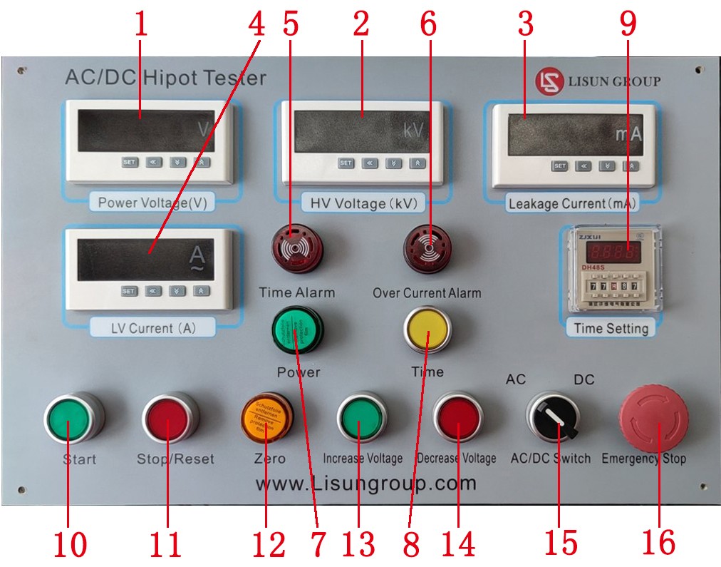
Panel Diagram (Image is for reference only; actual product may vary)
Power Supply Voltage Meter: Used to display the current power supply voltage;
High-voltage meter: Used to display the current actual high-voltage output;
Leakage Current Meter: Used to display the current high-voltage leakage current;
Low-voltage ammeter: Used to display the current actual leakage current; when the leakage current exceeds the set value, the device automatically cuts off the high-voltage output;
Timer Alarm: An alarm that sounds when the set time has elapsed;
Overcurrent Alarm: Used to display an alarm notification when a breakdown occurs during the voltage-boosting process;
Power Indicator Light: This light turns on when the cabinet is powered on;
Time Switch: Used to activate the time relay to measure the withstand time;
Timer Settings: Setting the duration;
Start Button: Starts the device;
Stop/Reset: Stops output; press the Stop button to reset;
Zero-point indicator light: During automatic voltage increase, press the stop button; when the voltage drops to its lowest point, this indicator light turns on. During manual voltage decrease, this indicator light turns on when the voltage reaches its lowest point; during automatic voltage decrease, this indicator light turns on when the voltage reaches its lowest point after the withstand time has elapsed;
Boost Button: Press this button to manually increase the voltage;
Voltage Reduction Button: Press this button to manually reduce the voltage;
AC/DC Switch Knob: Turn to switch between AC and DC;
Emergency Stop Button: Pressing this button cuts off all power to the equipment.
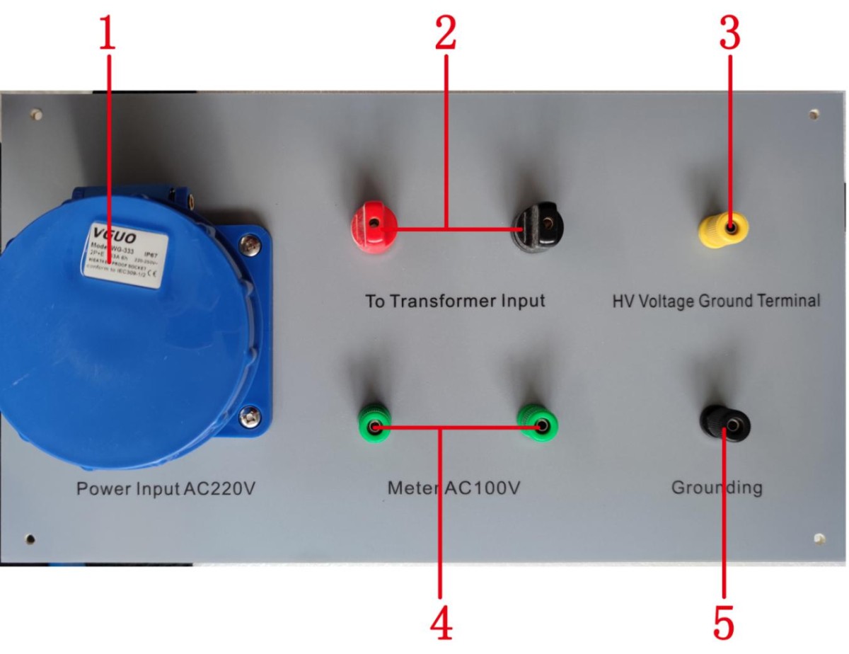
Rear Panel Diagram (Image is for reference only; actual product may vary)
AC 220 V input power supply port: Connects to a 220 V power source to supply power to the device’s main circuit and control circuit;
To the Voltage Transformer input port: Used to supply a low-voltage input of 0–200 V to the test Voltage Transformer;
High-Voltage Grounding Port: Used for protection and safety grounding when the equipment is under high voltage;
Voltage Measurement Output Port: Used to monitor the magnitude of the output voltage at the high-voltage end of the Voltage Transformer;
Ground Terminal: Used for the protection and safety grounding of the equipment.
Instructions for Using Digital Current and Voltage Meters
Meter Settings: The high-voltage voltmeter D1F is set for overvoltage, and D2F is set for the automatic voltage increase.
4.1 Programming and Use
1. Описание панели
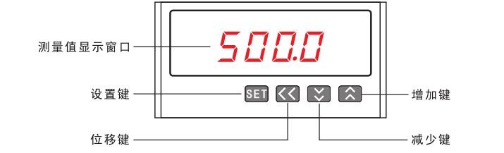
2. Описание кнопок
SET button: Press the SET button to enter programming mode; in programming mode, use it to save and return to the menu item.
Shift key: In programming mode, use this key to exit programming mode when on a menu item, and to move the cursor one position to the left when editing parameter values.

Down Arrow Key: In programming mode, use this key to scroll down through menu items when selecting them; when modifying parameters,

When used as a numeric value, it decrements the parameter value.
Increase Key: In programming mode, this key is used to scroll up through menu items when selecting them, and to increment parameter values when editing them.

3. Отображение инструкций

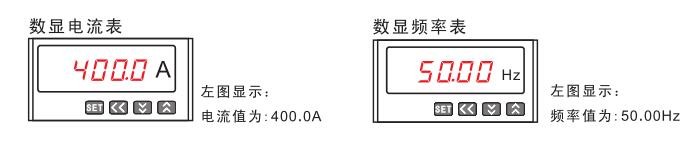
4. Структура меню
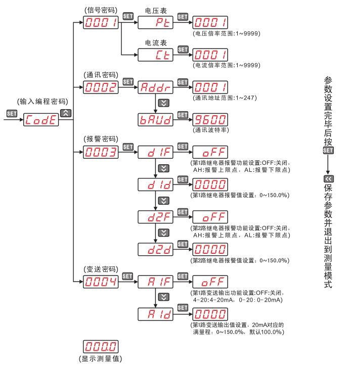
5. Описание меню
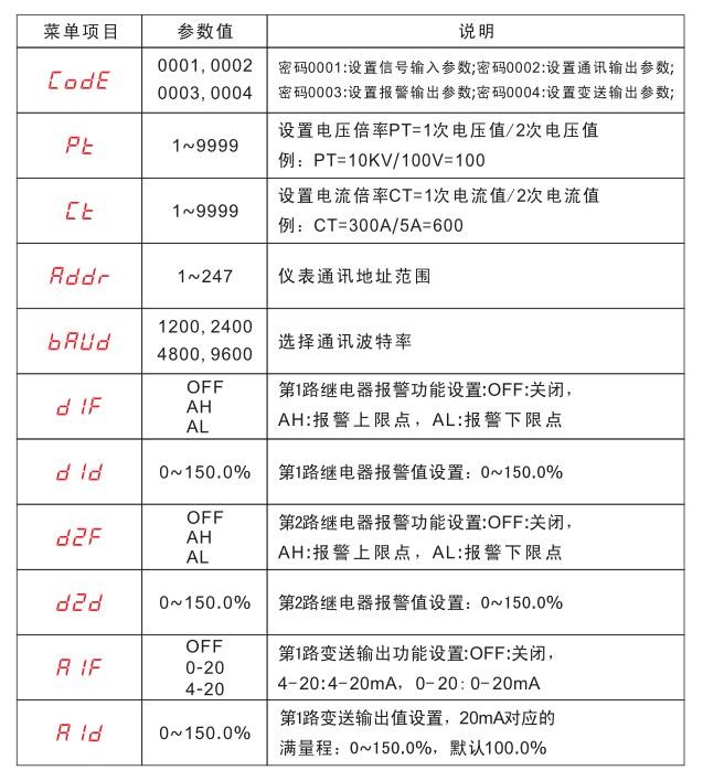
In programming mode, the instrument provides four menu items: signal input, communication output, digital alarm output, and analog transmitter output. The programming password for signal input is 0001; for communication output, it is 0002; for digital output, it is 0003; and for analog output, it is 0004.
The icons describing the menu options are as follows:
6. Примеры программирования
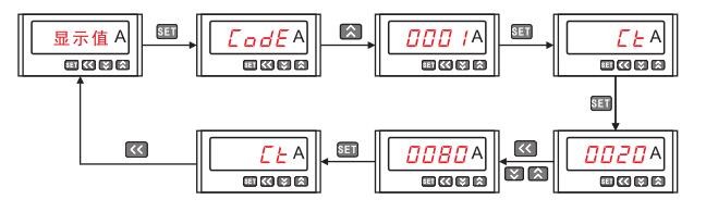
Before using any meter for the first time, please verify that its parameters match those of the power distribution system in which it will be installed. The factory default settings are listed on the label on the back of each meter. If the parameters do not match, you can use the four buttons on the panel to adjust the meter’s internal settings to meet the requirements of the power distribution system.
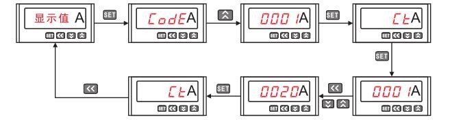
The factory specification for the AC digital ammeter is AC 5A (CT = 1). If the user connects a 100A/5A current transformer, the CT parameter should be adjusted to 20 (CT = 100A/5A = 20).
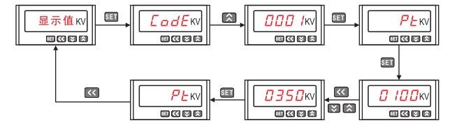
The factory specification for the AC digital voltmeter is AC 10 kV/100 V (PT = 10 kV/100 V = 100). If the user switches to an external 35 kV/100 V current transformer, the PT parameter should be changed to 350 (PT = 35 kV/100 V = 350).
(3) The factory specification for the digital DC ammeter is DC 100 A/75 mV (CT = 100/5 = 20).if the user switches to an external 400 A/75 mV shunt, the CT parameter should be changed to 80 (CT = 400/5 = 80).
Instructions for Use and Precautions
Wiring Procedure for AC Voltage Testing:
1. Connect the backplate to the AC 220V mains power supply using the power cord.
Connect one end of the test lead to the backplane output terminal ○,2), and the other end to the input terminal of the Voltage Transformer;
connect one end of the test lead to the backplane ○,3), and the other end to the high-voltage tail of the Voltage Transformer;
Connect one end of the test lead to the backplane ○,4), and the other end to the test transformer’s instrument terminal;
Connect the ground wire to the backplane (○,5), and connect the other end to ground;
Connect one end of the high-voltage lead to the high-voltage terminal of the test transformer and the other end to the test specimen; check the connections, and after confirming they are correct, turn on the main 220 V AC circuit breaker;
2. Open the main power circuit breaker on the side of the cabinet by lifting it upward, then turn ○,16) clockwise to release it. At this point, the power voltmeter (○,1) on the control panel will display the supply voltage, and ○,2) and ○,3) ○,4) digital display shows readings, ○,11) the start button indicator lights up, ○,12) the zero indicator lights up; ○,7) the power indicator lights up;
Following the instructions in Section IV, “Digital Display Meter User Manual,” or the instructional video, set the protection thresholds for the ammeters ○,3) and ○,4); set ○,9) to the required withstand time;
After confirming the settings are correct, turn ○,15) to the “AC” position and press the ○,11) start button. You will hear a “click” as the contactor engages. Press and hold the ○,13) voltage increase button to raise the voltage, and observe the ○,2) high-voltage output meter and ○,3) ○,4) current meters all show changes in their readings;
After the voltage has risen to the desired value, release the ○,13) voltage-increase button, press the ○,8) timer button to start the withstand voltage duration test, and ○,9) displays the withstand voltage duration;
(Note: 1. Check the test site and the ammeter for any abnormalities. If any are found, quickly press the emergency stop button (○,16) to stop the device. 2. If overcurrent protection is triggered for the test specimen, the ○,6) protection buzzer will sound, indicating that the test specimen has failed the test; press the ○,12) Stop/Reset button to silence the buzzer.)
However, once the withstand time has elapsed, the buzzer at ○,5) will sound, indicating that the test specimen has passed the withstand voltage test; press the timer button at ○,8) to stop the buzzer, and press and hold the voltage reduction button at ○,14) to reduce the voltage;
When the voltage drops to ○,12) and the zero indicator lights up, press the ○,11) stop button, flip the main power switch on the side of the cabinet to the off position to disconnect the AC 220 V mains power, and discharge the test specimen. At this point, all test leads can be removed;
The procedure for DC testing is the same; the only points to note are: 1. Remove the shorting rod from the test transformer; 2. Rotate the (○, 15) switch to the DC position;
HIPOT Series Power Frequency Withstand Voltage Test Sets
Обзор
The HIPOT series power-frequency withstand voltage test sets are a new product line manufactured in accordance with the Ministry of Machinery and Electronics’ “Power-Frequency Withstand Voltage Test Sets” standard, following extensive improvements to the original models of the same type. This series features a small footprint, light weight, compact design, comprehensive functionality, high versatility, and ease of use. It is particularly suitable for conducting insulation strength tests under power frequency or DC high voltage on various high-voltage electrical equipment, electrical components, and insulating materials in power systems, industrial and mining enterprises, and research institutions. It is an indispensable piece of equipment for high-voltage testing.
Структура продукта
The HIPOT series power-frequency withstand voltage test units feature a single-frame core structure. The primary winding is wound around the core, with the high-voltage winding on the outside; this coaxial arrangement reduces magnetic leakage flux, thereby increasing the coupling between the windings. The product’s housing is designed in an octagonal shape that fits the core perfectly, giving the unit an elegant and stylish appearance. Figure 1 shows the external structure, and Figure 2 shows the internal structure.
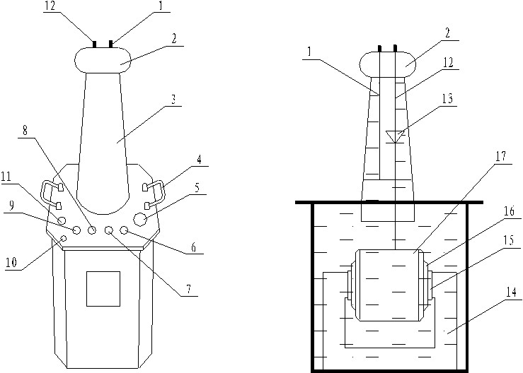
Figure 1: Schematic Diagram of the External Structure of a Voltage Transformer Figure 2: Internal Structure Diagram of a Single Power-Frequency Withstand Voltage Test Set
1-Shorting rod D 2-Equalizing ball 3-High-voltage bushing 4-Voltage Transformer handle
5—Oil valve; 6–7—Secondary pressure inputs a, x; 8–9—Measurement terminals E, F
10- Voltage Transformer Housing Ground Terminal 11- High-Voltage Terminal X 12- High-Voltage Output A
13-High-Voltage Silicon Stack 14-Voltage Transformer Oil 15-Iron Core
16-Secondary low-voltage winding 17-Measuring winding 18-Secondary high-voltage winding
In a HIPOT power-frequency withstand voltage test set, a and x are the low-voltage input terminals, E and F are the instrument measurement terminals, and A and X are the high-voltage output terminals.
Как это работает
The HIPOT series power-frequency withstand voltage test sets are designed for single-phase Voltage Transformers with connection group I. I. Connect a 220 V power supply (380 V for units rated at 10 kVA or higher) to the ∕XC∕TC series control cabinet (a device specifically designed for our company’s power frequency withstand voltage test sets; please refer to the specific user manual for detailed information). Using the Voltage Regulator inside the control cabinet(external for capacities of 50 kVA and above) to 0–200 V (or 0–400 V), which is then output to the primary winding of the HIPOT power frequency withstand voltage test set. Based on the principle of electromagnetic induction, the high voltage required for testing is generated in the high-voltage winding of the HIPOT power frequency withstand voltage test set.
1. See Figure 3 for a schematic diagram illustrating the operating principle of a single HIPOT high-voltage tester.
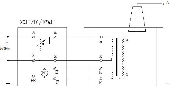
Figure 3: Schematic Diagram of a Single-Unit HIPOT Power-Frequency Withstand Voltage Tester
2. Figure 4 shows the schematic diagram of a single HIPOT power-frequency withstand voltage test unit. In the figure, a high-voltage silicon stack is installed inside the high-voltage bushing and connected in series in the high-voltage circuit to perform half-wave rectification, thereby generating a high-voltage DC output. When the high-voltage silicon diode stack is short-circuited using a shorting rod, a power-frequency high voltage is generated, resulting in AC output; when the shorting rod is removed, the unit operates in DC output mode.
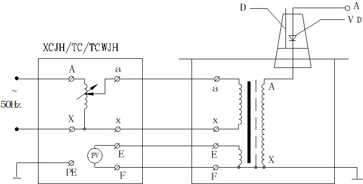
Figure 5 illustrates the wiring principle for cascading three power-frequency withstand voltage test units to achieve a higher voltage. Cascaded power-frequency withstand voltage test systems offer significant advantages because the entire system consists of several individual units. Each individual unit has a small capacity, low voltage, and light weight, making them easy to transport and install. Not only can they be connected in series to achieve a combined output voltage several times higher than that of a single unit, but they can also be separated into several sets of standalone units for individual use. The entire system requires a small investment and is cost-effective. In Figure 5, each unit of the power-frequency withstand voltage test set in the first and second stages has excitation windings A1, C1 and A2, C2. In the basic schematic diagram of the cascaded test transformers, the low-voltage power supply is applied to the primary winding a1x1 of power-frequency withstanding voltage test unit I. The output voltage of each individual test transformer I, II, and III is V. The excitation windings A1 and C1 supply power to the primary winding of the second-stage power-frequency withstand voltage test unit II; the excitation windings A2 and C2 of the second-stage power-frequency withstand voltage test unit II supply power to the primary winding of the third-stage power-frequency withstand voltage test unit III. The enclosures of the second-stage power-frequency withstand voltage test set II and the third-stage power-frequency withstand voltage test set III are at high potentials relative to ground of 1 V and 2 V, respectively; therefore, their enclosures are insulated from ground, while the enclosure of the first-stage power-frequency withstand voltage test set I is grounded. Thus, the rated output voltages to ground for the first-, second-, and third-level power-frequency withstand voltage test units are 1 V, 2 V, and 3 V, respectively; their rated capacities are 3P, 2P, and 1P, respectively.
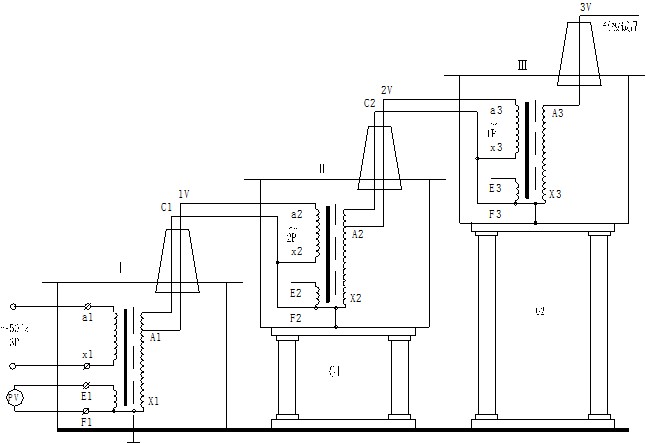
Figure 5: Schematic Diagram of a Cascade Connection of Three Power-Frequency Withstand Voltage Test Units
In the figure: P – Capacity (kVA); V – Voltage (kV); G1, G1 – Insulation supports
The high-voltage silicon diode stack in the high-voltage bushing of the HIPOT power-frequency withstand voltage test set is not shown; its operating principle is the same as that illustrated in the figure above.
Инструкции по использованию
The wiring diagram for the HIPOT power-frequency withstand voltage test set, used to perform power-frequency withstand voltage tests on test specimens, is shown in Figure 6.
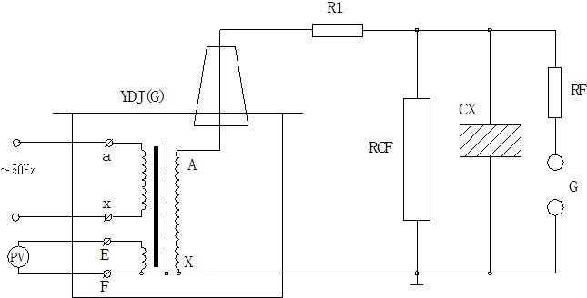
Figure 6: Wiring Diagram for Power Frequency Withstand Voltage Test of Test Specimens
In the figure: R1 – Current-limiting resistor; RCF – RC voltage divider; RF – Ball gap protection resistor
G – Ball clearance CX – Test specimen
Note: The high-voltage tail must be reliably grounded.
In a power-frequency withstand voltage test, the current-limiting resistor R1 should be selected based on the rated capacity of the power-frequency withstand voltage test set. For example, when the rated output current on the high-voltage side is between 100 and 300 mA, R1 can be set to 0.5–1 Ω/V (test voltage); when the rated output current on the high-voltage side is 1 A or higher, a value of 1 Ω/V (test voltage) may be used. Water resistors are commonly used as current-limiting resistors; the tube length may be calculated based on 150 kV/m, and the tube diameter should provide sufficient thermal capacity (method for preparing water resistor solution: add an appropriate amount of copper sulfate to distilled water to achieve various resistance values).
Spark gap and protective resistor: When the voltage exceeds the spark gap set point (typically 110%–120% of the test voltage), the spark gap discharges, thereby protecting the test specimen. The spark gap protective resistor may be selected based on the formula 1 Ω/V (test voltage).
In power-frequency withstand voltage tests, the voltage measured on the low-voltage side (instrument voltage) is not entirely accurate. This is due to the presence of leakage reactance in the power-frequency withstand voltage test set; this leakage reactance inevitably causes a voltage drop or capacitive rise, resulting in the voltage across the test specimen being lower or higher than the voltage indicated by the low-voltage-side voltmeter. During a power-frequency withstand voltage test, the voltage across the test specimen is higher than the output voltage of the test set—this is known as the capacitive rise phenomenon. During an induced voltage withstand test, a voltage drop must occur across the leakage reactance of the power-frequency withstand voltage test set. To accurately measure the voltage applied to the test specimen, an RCF resistor-capacitor voltage divider is often connected to the high-voltage side to measure the voltage (see Figure 6).
Precautions for Performing Power-Frequency Withstand Voltage Tests:
Test personnel should clearly define their respective roles and establish communication procedures. A designated person should be responsible for overseeing safety at the site and monitoring the condition of the test specimens.
The test specimen must first be thoroughly cleaned and completely dry to prevent damage to the specimen and errors in the test results.
For large-scale tests, an open-circuit test should generally be performed first. This involves raising the voltage to the test voltage without connecting the test specimen, calibrating various instruments, and adjusting the ball gap.
The rate of pressure increase must not be too fast, and sudden pressure surges must be prevented. For example, the Voltage Regulator must not be suddenly switched on when it is not at the zero position. The power supply must also not be suddenly cut off; generally, the circuit breaker should be tripped when the Voltage Regulator has dropped to the zero position.
When the voltage rises to the test voltage, start timing; only after 1 minute has elapsed and the voltage has been rapidly reduced to less than one-third of the test voltage may the power be disconnected.
During a boost or withstand voltage test, if any of the following abnormal conditions are observed, the voltage must be reduced immediately and the power supply disconnected. Stop the test and investigate the cause: (1) The voltmeter needle fluctuates significantly; (2) Insulation is found to be scorched or emitting smoke; (3) An abnormal noise is heard coming from the test specimen.
Insulation resistance should be measured before and after the withstand voltage test to check the condition of the insulation.
2. The wiring diagram for the HIPOT power-frequency withstand voltage test set when performing DC withstand voltage or leakage tests on the test specimen is shown in Figure 7.
Note: For this test, the shorting rod “D” should be removed first, as shown in Figure 7.
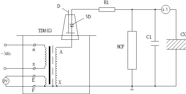
Figure 7: Wiring Diagram for High-Voltage DC Leakage Test
In the figure: VD – High-voltage silicon diode stack R1 – Current-limiting resistor C1 – High-voltage filter capacitor
RCF – RC voltage divider CX – Test specimen uA – Microamp range with protection
In leakage tests, the current-limiting resistor R1 is selected such that, at the rated output voltage, the short-circuit current at the output terminal does not exceed the maximum rectification current of the high-voltage silicon stack. For example, if the maximum rectification current of the high-voltage silicon stack is 100 mA and it is used in a 60 kV test setup, the current-limiting resistor is selected as R1 = 60 / 0.1 = 600 kΩ. The current-limiting resistor should also have sufficient capacitance and surface discharge distance. The high-voltage filter capacitor C1 is generally selected to be between 0.01 and 0.1 μF; however, C1 may be omitted when the capacitance of the test specimen is very large.
Leak Test Procedures and Precautions:
Before the test, check to ensure that the test specimen is de-energized, properly grounded and discharged, and that all external connections are clean. Take strict precautions to prevent the test voltage from being applied to areas where personnel are working.
After connecting the test setup, verify that all connections are correct before applying voltage. Pay special attention to checking the safety distances between high-voltage equipment and leads and the ground, as well as between the equipment and operating personnel; ensure that the test specimen’s casing is reliably grounded; and conduct the test in accordance with the provisions of the safety procedures.
For equipment with high capacitance, the voltage should be increased slowly to prevent the charging current from damaging the microampere meter. If necessary, apply voltage in stages and record the stable readings of the microampere meter at each voltage level.
During the test, closely monitor the test specimen, the test setup, and the microampere meter. If any abnormal phenomena, such as breakdown or flashover, occur, immediately reduce the voltage, disconnect the power supply, investigate the cause, and record the details.
After the test is complete, reduce the voltage, and after disconnecting the power supply, thoroughly discharge the test specimen and the test apparatus itself.
Важные замечания
Connect the test circuit according to the test you are conducting. The enclosure of the power-frequency withstand voltage test set and the enclosure of the control system must be reliably grounded. The X terminal (high-voltage terminal) of the high-voltage winding of the test transformer and the F terminal of the measurement winding must be reliably grounded.
When performing cascade testing, the low-voltage winding of the second- and third-stage power-frequency withstanding voltage test sets is connected to the X terminal; the F terminal of the test winding and the X terminal (high-voltage end) of the high-voltage winding are both connected to the enclosure of the power-frequency withstanding voltage test set at that stage. The enclosures of the second- and third-stage power-frequency withstand voltage test units must be grounded via insulating supports.
Before turning on the power, the operating system’s Voltage Regulator must be set to zero before power can be applied, the circuit breaker closed, and the voltage increased.
Start from zero and rotate the Voltage Regulator handwheel at a constant speed to increase the voltage. The following voltage-rising methods are available: the rapid voltage-rising method (i.e., a 20-second step-by-step increase); the slow voltage-rising method (i.e., a 60-second step-by-step increase); and the extremely slow voltage-rising method. Starting from zero, increase the voltage according to the specified method and rate until it reaches 75% of the required rated test voltage. Then, increase the voltage at a rate of 2% of the rated test voltage per second until the required test voltage is reached, while closely monitoring the readings on the measuring instruments and the condition of the test specimen. If any abnormalities in the measuring instrument readings or the condition of the test specimen are detected during the voltage ramp-up or test process, the voltage must be reduced immediately, the power supply disconnected, and the cause investigated.
After the test is complete, return the Voltage Regulator to the zero position at a constant speed within a few seconds, and then turn off the power.
This product must not be operated beyond its rated parameters. Unless absolutely necessary for testing purposes, never apply or remove power.
When using this product for high-voltage testing, in addition to familiarizing yourself with this manual, you must strictly comply with relevant national standards and operating procedures. Refer to GB 311.1–97, “Insulation Coordination and High-Voltage Testing Techniques for High-Voltage Transmission and Transformation Equipment,” and the “Regulations on Preventive Testing of Electrical Equipment,” among others.
Selecting the Capacity of a Power Frequency Withstand Voltage Test System
Formula for determining the rated power Pn of a power-frequency withstand voltage test set: Pn = KVn²ωCt × 10⁻⁹
In the formula: Pn—-Nominal capacity of the power frequency withstand voltage test set (kVA)
Vn—–RMS value of the rated output high voltage of the power frequency withstand voltage test set (kV)
K——-Safety factor. When K ≥ 1 and the rated voltage Vn ≥ 1 MV, K = 2; when the rated voltage is lower, a higher value for K may be selected.
Ct——Capacitance of the test specimen (PF)
ω—-angular frequency, ω = 2πf, f—–frequency of the test power supply
The capacitance Ct of the device under test can be measured using an AC bridge. Ct varies widely depending on the type of device. Typical values are shown in the table below:
| Simple Bridge-Type or Suspension Insulators | Tens of microfarads |
| Simple Graded Casing | 100–1000 пФ |
| Преобразователь напряжения | 200–500 пФ |
| Voltage Transformers < 1000 kVA | – 1000 pF |
| Voltage Transformers > 1000 kVA | 1000 – 10000 пФ |
| High-Voltage Power Cables and Oil-Impregnated Paper Insulation | 250–300 pF/m |
| Газовая изоляция | – 60 PF/m |
| Enclosed Substation, SF6 Gas Insulation | 100 – 10000 пФ |
Select a different (appropriate) safety factor K for each test voltage Vn. The K values selected for the various Vn values listed above are provided for reference.
Vn = 50–100 kV, K = 4; Vn = 150–300 kV, K = 3; Vn > 300 kV, K = 2
Требования безопасности:
Пожалуйста, ознакомьтесь со следующими мерами предосторожности, чтобы избежать травм и повреждения данного изделия или любых других связанных с ним изделий. Во избежание потенциальных опасностей, данное изделие должно использоваться только в пределах указанных ограничений.
To prevent fire or personal injury, maintenance may only be performed by qualified technicians.
Use the appropriate power cord. Use only the power cord designed specifically for this product and that meets its specifications.
Connect and disconnect properly. When the test leads are connected to live terminals, do not connect or disconnect them carelessly.
Product Grounding. In addition to grounding via the power cord’s grounding conductor, the grounding terminal on the product’s enclosure must be grounded. To prevent electric shock, the grounding conductor must be connected to ground. Before connecting to the product’s input or output terminals, ensure that the product is properly grounded.
Pay attention to the ratings of all terminals. To prevent the risk of fire or electric shock, observe all ratings and markings on this product. Before connecting this product, read the user manual for more information about the ratings.
Не используйте прибор без установленной крышки. Если крышка или передняя панель сняты, не используйте данное изделие.
Используйте соответствующий предохранитель. Используйте только предохранители, соответствующие типу и номинальным характеристикам данного изделия.
Avoid contact with exposed circuits and live metal parts. Do not touch exposed contacts or parts while the product is energized.
Do not operate the unit if you suspect a malfunction. If you suspect that this product is damaged, have it inspected by our service personnel; do not continue to operate it.
Не эксплуатируйте в условиях повышенной влажности.
Не работайте во взрывоопасных средах.
Поверхность изделия должна быть чистой и сухой.
Условия безопасности

Warning: Warning statements indicate situations or practices that could result in injury or death.
Caution: The word “Caution” indicates situations or practices that may cause damage to this product or other property.