
 Английский
 中文简体
中文简体 Русский
 Español
 Português
 Türkçe
 العربية
 Deutsch
 Polski
 Italiano
 Français
 한국어
한국어 ไทย
ไทย Tiếng Việt
 日本語
日本語





























EFT Иммунитет Измерение
Руководство пользователя
Применимый LISUN models: EFT-CLAMP、EFT-DESK、EFT61000-4,EFT61000-4-100A、EFT61000-4-32A、EFT61000-4А.EFT61000-4A-100A、EFT61000-4A-32A
1. Распаковка и базовое ознакомление с оборудованием.
1.1 Основные технические характеристики
| LISUN Модель | EFT61000-4 | EFT61000-4A | EFT61000-4-32A | EFT61000-4A-32A | EFT61000-4-100A | EFT61000-4A-100A |
| Выходное напряжение | 0–5 кВ | 0–6 кВ | 0–5 кВ | 0–6 кВ | 0–5 кВ | 0–6 кВ |
| Частота импульсов | 0.1 kHz to 1200 kHz, continuously adjustable | |||||
| Импульсная полярность | Positive/Negative, Automatic Alternation Between Positive and Negative | |||||
| внутреннее сопротивление | 50 Ω ±20%, 1000 Ω ±20% | |||||
| Время нарастания импульса | 5 нс ±30% | |||||
| Pulse Width (at 50 Ω) | 50 нс ±30% | |||||
| Pulse Width (at 1 kΩ) | от 35 нс до 150 нс | |||||
| Период импульсной последовательности | От 1 мс до 1000 мс | |||||
| Number of Pulse Strings | 1-255 | |||||
| Время тестирования | 1–9999 с | |||||
| Тестирование функций | Set the test mode or IEC class as desired | |||||
| Сеть связи и развязки | Встроенный 16А, 3-фазный/5-проводной | Встроенный 32А, 3-фазный/5-проводной | Внешний 100А, 3-фазный/5-проводной | |||
| Электропитание | Напряжение переменного тока 220 В (110 В опционально) ±10%, 50/60 Гц | |||||
1.2 Распаковка, осмотр и проверка аксессуаров
1.2.1 Распаковка и визуальный осмотр
При распаковке устройства обращайтесь с ним осторожно, чтобы не поцарапать корпус острыми предметами. После распаковки сначала осмотрите внешний вид устройства, чтобы убедиться в отсутствии видимых деформаций или вмятин, а также в том, что кнопки не повреждены и не расшатаны.
Если вы обнаружите какие-либо повреждения или деформации оборудования или принадлежностей, не включайте питание. Немедленно свяжитесь с нами.
1.2.2 Главный компьютер и принадлежности
Main Units: ① EFT61000-4 EFT Immunity Measurement; ② EFT-DESK Standard Test Bench; ③ EFT-CLAMP Capacitive Coupling Clamp.
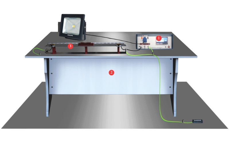
Рисунок 1
Note: Items ② and ③ are optional.
The EFT-CLAMP Capacitive Coupling Clamp is used to test I/O lines.
Standard Accessories: ① Power cord; ② or ③ EUT power input cable (choose one);④ EUT power output, used to connect the EUT to the instrument’s front panel; ⑤ coaxial cable, used to connect to an external oscilloscope for waveform monitoring; ⑥ ground wire, used to connect to the PGND protective ground terminal; ⑦ discharge tube, used to check whether the instrument produces a pulse output in the event of a device malfunction.
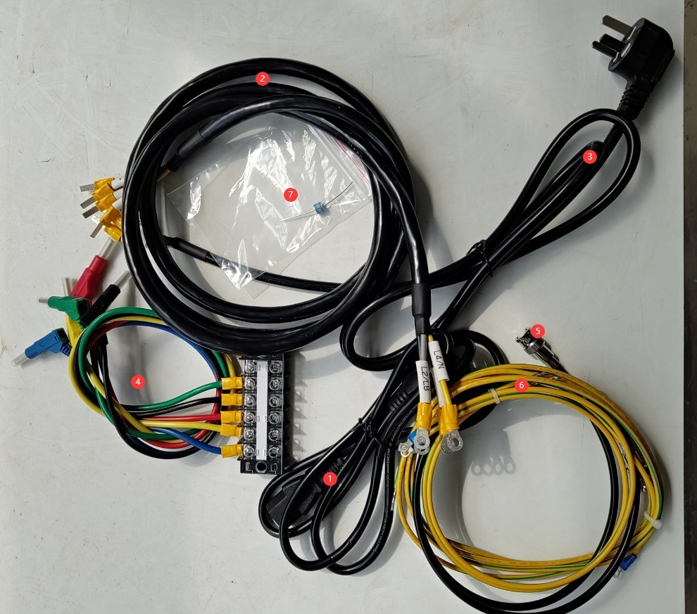
Рисунок 2
Ссылки для скачивания цифрового руководства пользователя, гарантийного талона и других документов были отправлены вам по электронной почте. Пожалуйста, скачайте их как можно скорее. Если вы пропустили письмо, пожалуйста, свяжитесь с нами, чтобы запросить ссылки для скачивания еще раз.
2. Меры предосторожности.
2.1 Рекомендации по размещению
Установите его на устойчивой рабочей поверхности; избегайте наклона или переворачивания и держите подальше от источников вибрации;
Оборудование должно быть размещено на расстоянии не менее 1000 мм от стен и окружающих конструкций (таких как другое испытательное оборудование и стеллажи) для облегчения технического обслуживания; перед оборудованием должно быть оставлено не менее 2000 мм свободного пространства для обеспечения бесперебойной работы, и в окружающей зоне не должно быть никаких препятствий.
2.2 Стандарты безопасности при работе с высоковольтным оборудованием
2.2.1 Проверка безопасности
Убедитесь в совместимости блока питания с оборудованием, проверьте правильность заземления блока питания и убедитесь в отсутствии повреждений или ослабления заземляющего провода;
Grounding Requirements: The host unit’s protective grounding terminal (PGND) must be connected to the ground reference plane; the grounding resistance must be ≤4 Ω; the grounding cable must be securely connected, with no looseness or breaks;
The ground reference plane must be connected to the grounding metal plate and to the ground; all ground connections must have low impedance to prevent potential differences from occurring during discharge.
2.2.2 Требования безопасности к рабочим процедурам
Операторы должны пройти профессиональную подготовку и ознакомиться с данным руководством и соответствующими стандартами. Неспециалистам запрещается эксплуатировать или разбирать оборудование. Оборудование содержит высоковольтные цепи; открытие крышки может представлять опасность поражения электрическим током. Для ремонта обращайтесь к техническому персоналу производителя.
Once the equipment is powered on, do not touch the terminal blocks, cables, or the EUT;
Операторы должны следить за тем, чтобы их руки были сухими и не содержали металлических украшений; рекомендуется использовать утепленные перчатки во время работы.
During testing, unauthorized personnel are prohibited from remaining within 1 meter of the EUT to prevent accidental electric shock or interference from electrical discharges;
Перед заменой электродов необходимо сначала убедиться, что высоковольтное напряжение отключено (индикатор ВН погас), и подождать не менее 5 минут, чтобы убедиться, что внутренний высоковольтный конденсатор полностью разряжен;
Do not eat or drink during the test to prevent accidents caused by electric shocks;
Если в тестировании участвует несколько человек, четко определите роли и обязанности и подтвердите их друг с другом до начала тестирования, чтобы избежать ошибок.
Другие 2.3
По вопросам, не охваченным данным руководством, пожалуйста, проявляйте осторожность или свяжитесь с нами.
3. Подготовка к тесту
3.1 Test Environment and Wiring for Power Cord Immunity Testing
3.1.1 Front of the Instrument
① Grounded metal plate, connected to ground via a conductor; ② Wooden test bench; ③ Grounded reference plane, connected to the grounded metal plate via a ground wire;④ Can be connected to the EUT; ⑤ Can be connected to the EUT; ⑥ Connect the protective ground terminal of the SGND signal line on the front panel of the instrument to the reference ground plane; ⑦ Insulated support; ⑧ EUT test specimen.
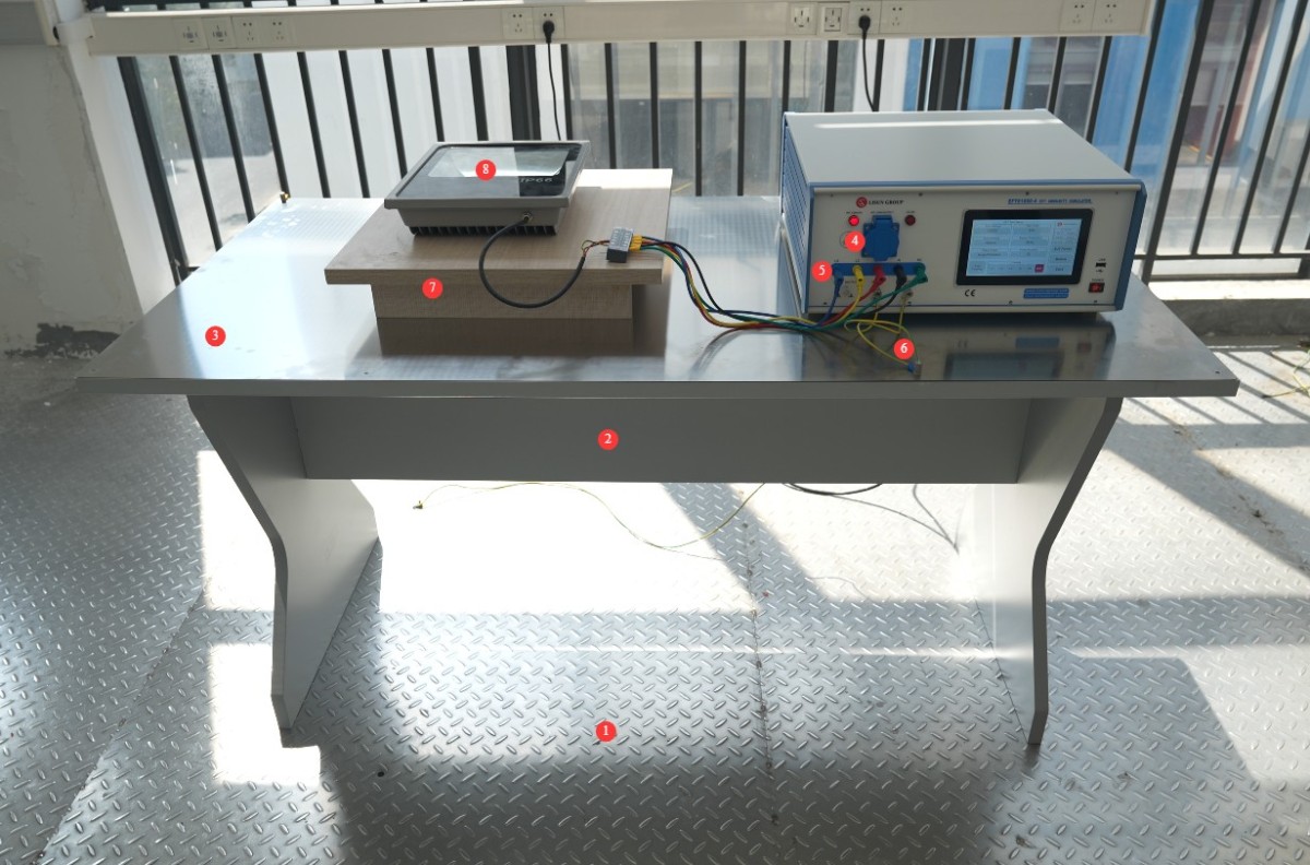
Рисунок 3
The grounding reference plane must meet the following dimensions: thickness ≥ 0.25 mm; it must be large enough to accommodate the EUT, instruments, coupling devices, and all accessories; and it must extend 10 cm beyond the edges on all four sides.
The EUT must be placed on the grounded reference plane using an insulating support with a thickness of 10 cm, and the distance between the bottom of the EUT and the grounded reference plane must be strictly maintained at 10 cm.
The instrument (including the coupling network) shall be placed directly on the grounded reference plane, at a distance of ≥0.5 m from the EUT; the EUT shall be located at a distance of ≥0.5 m from conductive structures such as laboratory walls and anechoic chamber walls.
The length of the power and signal cables connecting the EUT to the test equipment shall be maintained at 0.5 m ± 0.05 m; if the EUT has a built-in, non-detachable cable longer than 0.5 m, the excess length shall be folded (avoiding the formation of a flat loop) and placed 10 cm above the ground reference plane.
3.1.2 Back of the Instrument
① Power cord; ② EUT power input cable—please connect the EUT to a suitable power source; ③ PGND protective ground terminal—please connect to a grounded metal plate.
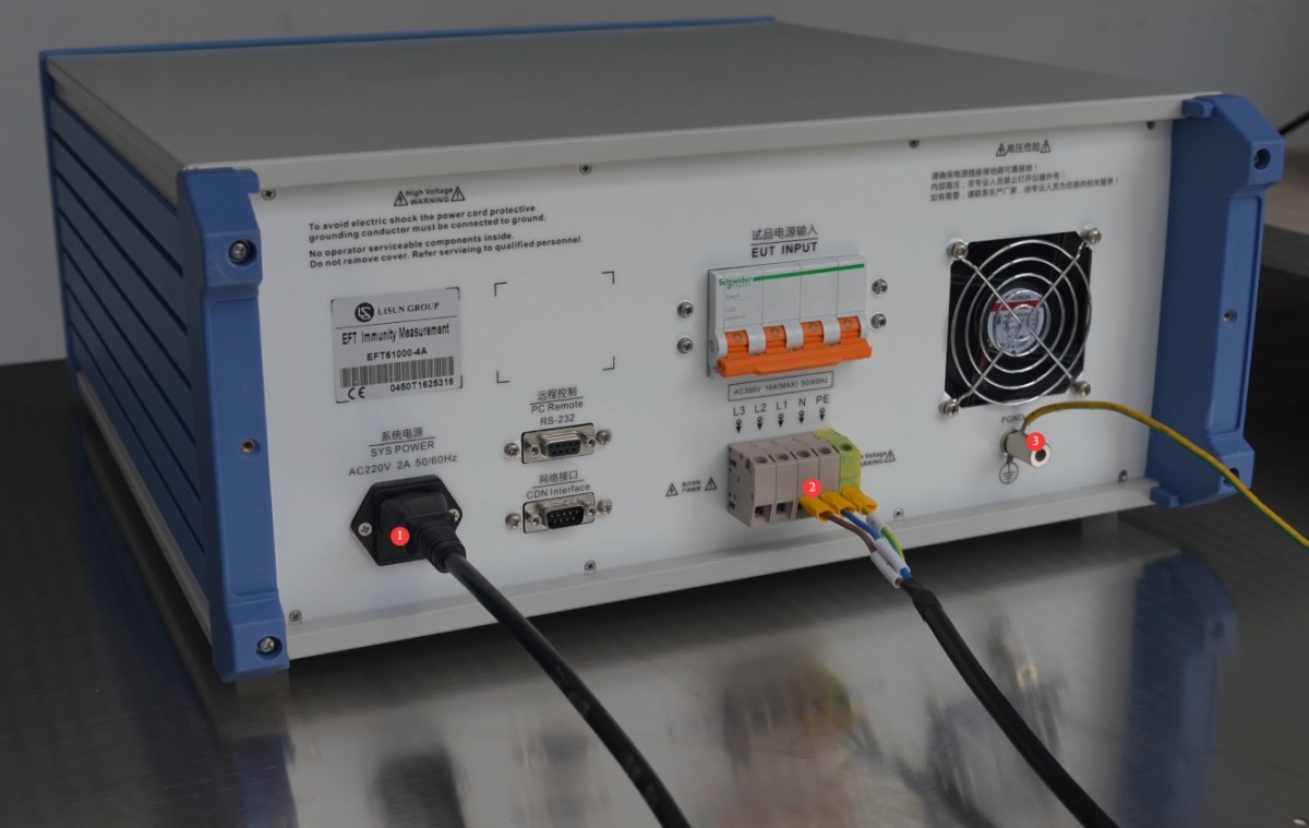
Рисунок 4
3.2 Test Environment and Wiring for IO Signal Line Immunity Testing
Place the Capacitive Coupling Clamp on the ground reference plane. ① Connect the ground terminal of the Capacitive Coupling Clamp to the ground reference plane; ② Connect the Capacitive Coupling Clamp to the BNC connector on the instrument’s front panel via a coaxial cable; ③ Route the I/O cable through the Capacitive Coupling Clamp.
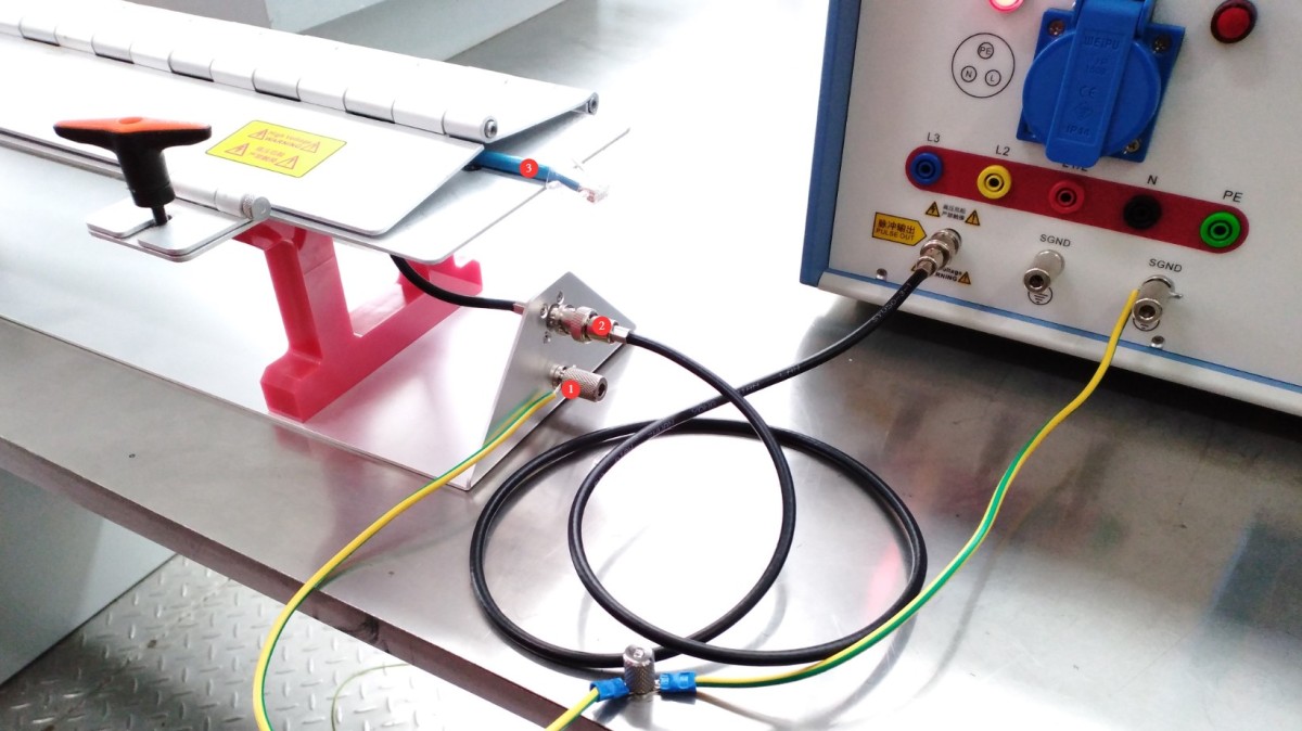
Рисунок 5
Route the EUT’s I/O cables through the capacitive coupling clamp, with one end of each cable connected to the EUT and the other to the AE (auxiliary) device. Place the EUT and the AE device on 10-cm-thick insulated supports, respectively.
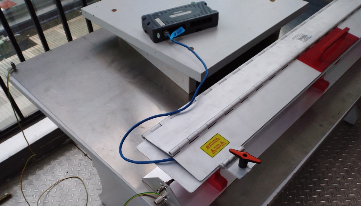
Рисунок 6
The distance between the AE equipment and the EUT must be ≥0.5 m, and its power cord must be connected to the power supply network via a decoupling network to prevent impulse interference from being conducted to auxiliary equipment.
3.3 Подтверждение параметров испытаний
| Имя параметра | Диапазон настройки | Standard Requirements (GB/T 17626.4-2018) |
| Испытательное напряжение | 0.25–5/6 kV (open circuit) | Power Ports: Levels 1–4 (1 kV/2 kV/4 kV/6 kV); I/O Ports: 1 and 2 corresponding to the power ports |
| Время тестирования | 1–9999 XNUMX секунд | The standard test duration is 60 seconds; custom durations are available upon request. |
| Период импульсной последовательности | 1–1000 мс | The default value is 300 ms, but it can be modified according to the test plan. |
| Частота повторения импульсов | 0.1–1200 кГц | Commonly used frequencies: 5 kHz, 100 kHz, 300 kHz |
| Угол фазы | 0–359°/Asynchronous | If there are no synchronization requirements, select “Asynchronous.” |
| Количество импульсов | 1-255 | The default is 75. The string length is calculated as (number of items – 1) / frequency of repetition. |
| Импульсная полярность | Positive/Negative/Alternating Positive and Negative | For routine testing, select “Alternating Positive and Negative” to cover all interference scenarios. |
3.4 Прогрев оборудования и самодиагностика
Turn on the power switch on the front panel of the host; the device enters standby mode, the power indicator lights up, and the cooling fan starts.
Подождите 5 минут, пока устройство прогреется, и убедитесь, что сенсорный экран работает нормально и нет сообщений об ошибках.
4. Введение в программу сенсорного экрана
4.1 Начальный экран
① General Usage Notes (Features are still being developed; no action is required at this time); ② System Information Screen; ③ Switch Between Chinese and English; ④ EFT Test Screen.

Рисунок 7
4.2 Экран системной информации
Test Logs: View or export historical test logs.
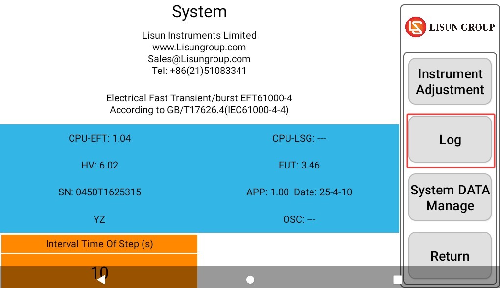
Рисунок 8
4.3 EFT Test Interface
① Test voltage and polarity settings; ② Test duration settings; ③ Pulse train period settings; ④ Pulse repetition frequency settings; ⑤ Phase angle settings; ⑥ Number of pulses settings; ⑦ Automatic coupling option, allowing you to select the required coupling lines all at once;⑧ Manual selection of coupling lines; single or multiple selections are possible; ⑨ Display of the EUT’s current electrical parameters; ⑩ Click to turn the EUT power on or off; ⑪ Click to start or stop the test.
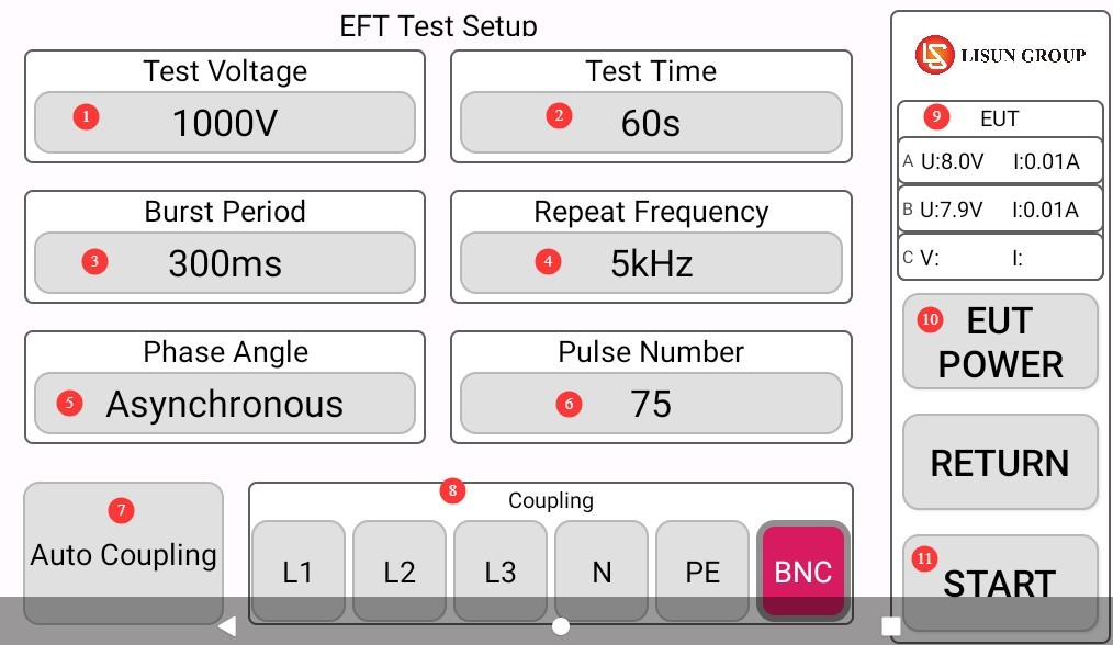
Рисунок 9
Note: Power port coupling: Select any combination of “L1,” “L2,” “L3,” “N,” and “PE”; Signal port coupling: Select “BNC”; Automatic coupling: Applies interference in the system’s preset order (L1 → L2 → L3 → N → PE → combination), suitable for comprehensive testing.
5. Fast Transient and Burst (FTB) Test
5.1 Рабочие процедуры
If the EUT requires power, close the EUT power input switch on the back of the device.
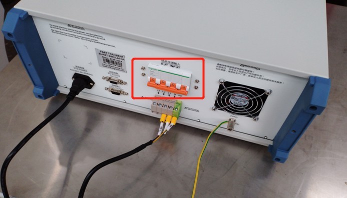
Рисунок 10
Set all test parameters according to sections 3.3 and 4.3.
Click “EUT POWER” to turn on the EUT power supply.
Click “START” to begin the test.
5.2 Определение того, прошло ли испытуемое устройство испытание
| Criteria Levels | Definition of Standards | Простое объяснение | Заявление о соответствии |
| Category A (Highest Requirements) | Performs normally within the limits specified by the manufacturer, the client, or the purchaser | During and after the test, the EUT’s functionality and performance were completely unaffected, with no abnormalities observed. | Fully meets the requirements; passed the test |
| Категория B | A temporary loss or reduction in function or performance that resolves on its own once the disturbance ceases, without requiring operator intervention | Temporary malfunctions (such as stuttering or brief data loss) may occur during the test, but normal operation will resume immediately after the pulse stops. | Generally considered acceptable and suitable for most non-critical equipment |
| Категория C | A temporary loss or reduction in functionality or performance that requires operator intervention to restore (e.g., restart, reset, reconfiguration) | After the test, the EUT was unable to return to normal on its own and required manual intervention to restore functionality. | This is generally considered nonconforming, unless otherwise specified in the product standard. |
| Категория D | Irreversible loss of functionality or reduced performance due to hardware or software damage, or data loss | The EUT has suffered a permanent failure, such as hardware damage, a software crash, or the loss of critical data that cannot be recovered. | Completely unsatisfactory; test failed |
6. Процедуры после испытаний
6.1 Тест остановлен
If the EUT is visibly damaged during the test, immediately tap “Stop Test” on the touchscreen, then tap “EUT Power” to turn off the EUT’s power.
If no abnormalities occur during the test, wait for the pulse test to complete automatically, then click “EUT Power” to turn off the EUT’s power.
Turn off the EUT input power supply switch on the back of the unit.
Wait 5 minutes to ensure that the high-voltage capacitors inside the host unit have fully discharged, then replace the EUT for testing, or turn off the host unit’s power.
6.2 Уборка и наведение порядка после тестирования
Очистите тестовый участок и протрите его сухой тканью; не используйте спирт или едкие чистящие средства.
Pulse testing is a destructive test; it does not automatically generate a test report, but the device automatically saves the test data. You can go to “System Information,” click “Test Log,” and export the corresponding test data to a USB flash drive via the USB port. The exported file is in TXT text format.
6.3 Хранение оборудования
6.3.1 Требования к краткосрочному хранению
Если оборудование используется ежедневно, после завершения каждого теста и очистки оборудования никаких дополнительных действий не требуется.
6.3.2 Требования к долговременному хранению
Если устройство не будет использоваться в течение длительного периода (более одного месяца), пожалуйста, отсоедините все кабели и накройте устройство пылезащитным чехлом, чтобы предотвратить скопление пыли.
Для предотвращения износа электрических компонентов (таких как конденсаторы и контакторы) устройство следует включать раз в месяц всего на полчаса.
7. Поиск и устранение распространенных проблем
7.1 Устройство не включается
Симптом: После включения выключателя питания устройство не реагирует (индикатор не загорается, вентилятор не вращается).
Возможные причины: ① Неправильное подключение или повреждение сетевого шнура; ② Ненормальное напряжение питания; ③ Перегоревший предохранитель; ④ Сгоревший варистор (MOV).
Solution: Ensure the power cord is intact and securely connected. Power supply issues—such as unstable voltage, excessively high voltage, or harmonic interference—can cause the fuse or varistor to burn out. We recommend using a regulated, clean sine-wave AC power supply to power the device. Replace the fuse or varistor with one of the same type.
На рисунке ниже показано расположение предохранителя:
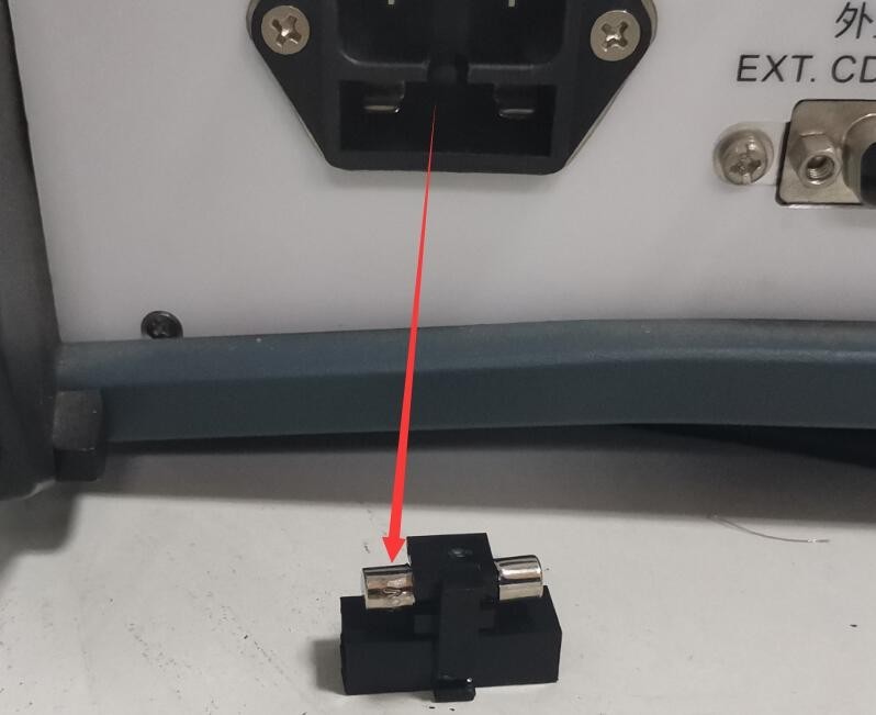
Рисунок 39
На следующем рисунке показано расположение варистора (MOV) внутри фильтрованного источника питания:
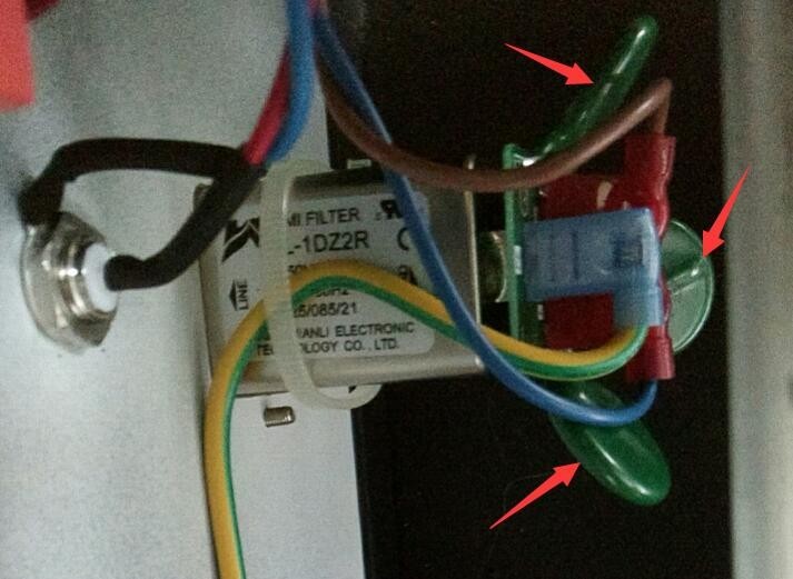
Рисунок 40
7.2 Автоматический перезапуск устройства
Симптом: Устройство автоматически перезапускается во время подачи импульсов.
Возможная причина: Заземляющий провод подключен неправильно.
Solution: Refer to Section 2.2.1. Connect the PGND grounding terminal on the back of the host to ground, and ensure that the grounding resistance is ≤4Ω. Otherwise, high voltage may not be safely dissipated, causing the device to automatically restart.
7.3 Pulse Phase Angle Test Failed
Symptom: The synchronization phase angle has been set, but the pulse test is not being performed according to the corresponding phase angle.
Возможная причина: блок питания тестируемого устройства не включен.
Procedure: The EUT must be powered by an AC source, and the EUT must be turned on during testing so that the pulse generator can detect the EUT’s power supply waveform and perform pulse testing according to the set phase angle.