
 Английский
 中文简体
中文简体 Русский
 Español
 Português
 Türkçe
 العربية
 Deutsch
 Polski
 Italiano
 Français
 한국어
한국어 ไทย
ไทย Tiếng Việt
 日本語
日本語





























Шкаф управления лампами накаливания/галогенными лампами
Руководство пользователя
Применимый LISUN models: DFX-WD20A
1. Распаковка и базовое ознакомление с оборудованием.
1.1 Основные технические характеристики
1.1.1 DFX Tungsten Filament Lamp Load Cabinet
Power Supply: Single-phase AC 220 ± 10% / 50 Hz with ground wire;
Digital Voltmeter: Range 0–300 V, accuracy ±0.5% ±2d;
Digital ammeter: Range 0–40 A, accuracy ±0.5% ±2d;
Digital Power Meter: Range 0–9 kW, Accuracy ±0.5% ±2d;
Load Configuration: Built-in 3 sets of multi-bulb 200W tungsten/halogen lamp combinations, with cyclic power supply;
Number of output channels: 1;
Load capacity: 7.5 kVA;
The maximum output current is 20 A; the load is automatically disconnected when the current exceeds 22 A;
The maximum output voltage is 300 V; when it exceeds 305 V, the load is automatically disconnected;
Selecting the number of tungsten filament lamps/halogen lamps: Each lamp has a power rating of 200 W, available in sets of 1, 2, 3, 4, 10, or 10 lamps;
Counter: Preset range of 0 to 999999;
Features a long-stick protection function: The upper limit for long-stick time can be preset from 0 to 99 seconds.
1.1.2 Испытательный стенд для проверки срока службы розеток и выключателей серии CZKS
| LISUN Модель | CZKS-3 | CZKS-3P | CZKS-3S | CZKS-3A |
| Рабочая станция | 2 розетки + 1 выключатель | розетка на 3 выходов | Переключатели 3 | 1 розетка + 2 выключателя |
| Тип привода | Pneumatic drive; customer-supplied air source: 0.8 MPa | |||
| Методы контроля | ПЛК + Сверхбольшой сенсорный экран | |||
| Время включения/выключения | 0–99.9 секунд в минуту (регулируемое значение) | |||
| Количество тестов | 0–999999 раз (предустановлено) | |||
| Тестирование | Linear: -40 to 110 mm (presettable); Rotation: 0 to 360° (presettable) | |||
| Скорость тестирования | Линейная скорость: 0–100 мм/с (предустановленная); Вращательная скорость: 0–90°/с (предустановленная) | |||
| Образец приспособления | Comes standard with a universal clamp that can be adjusted up and down (other special clamps can be custom-made according to customer requirements) | |||
| LISUN Модель | CZKS-6 | CZKS-6P | CZKS-6S | CZKS-6X |
| Рабочая станция | 3 розетки + 3 выключателя | розетка на 6 выходов | Переключатели 6 | Настраиваемое количество розеток и выключателей |
| Тип привода | Pneumatic drive; customer must provide their own air supply: 0.8 MPa | |||
| Методы контроля | ПЛК + Сверхбольшой сенсорный экран | |||
| Время включения/выключения | 0–99.9 секунд в минуту (регулируемое значение) | |||
| Количество тестов | 0–999999 раз (предустановлено) | |||
| Тестирование | Linear: -40 to 110 mm (presettable); Rotation: 0 to 360° (presettable) | |||
| Скорость тестирования | Линейная скорость: 0–100 мм/с (предустановленная); Вращательная скорость: 0–90°/с (предустановленная) | |||
| Образец приспособления | Comes standard with a universal clamp that can be adjusted up and down (other special configurations can be customized according to customer requirements) | |||
1.2 Распаковка, осмотр и проверка аксессуаров
1.2.1 Распаковка и визуальный осмотр
При распаковке устройства обращайтесь с ним осторожно, чтобы не поцарапать корпус острыми предметами. После распаковки сначала осмотрите внешний вид устройства, чтобы убедиться в отсутствии видимых деформаций или вмятин, а также в том, что кнопки не повреждены и не расшатаны.
Если вы обнаружите какие-либо повреждения или деформации оборудования или принадлежностей, не включайте питание. Немедленно свяжитесь с нами.
1.2.2 Основной блок и принадлежности
Load cabinet: 1 unit; CZKS life tester: 1 unit.
Standard accessories: 200W tungsten bulbs—52 in total (32 for the load cabinet, with the remaining 20 as spares).
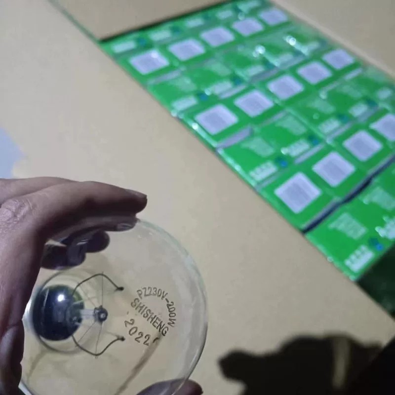
Рисунок 1
Примечание: LISUN switch life tester must be used in conjunction with an air compressor. Users may purchase one from LISUN or provide their own. If providing your own, please ensure it is capable of delivering compressed air at 0.8 MPa. An air hose with an 8 mm outer diameter is required for connection to the switch life tester.
Ссылки для скачивания цифрового руководства пользователя, гарантийного талона и других документов были отправлены вам по электронной почте. Пожалуйста, скачайте их как можно скорее. Если вы пропустили письмо, пожалуйста, свяжитесь с нами, чтобы запросить ссылки для скачивания еще раз.
1.3 Описание конструкции оборудования
1.3.1 Шкаф управления
Front of the load cabinet:
① Load (tungsten filament lamp) voltage display; ② Load current display; ③ Load power display; ④ Number of tests: the top line shows the current number of tests performed, and the bottom line shows the set total number of tests;⑤ Long-duration stick-on protection time: the top line shows the current load on-time, and the bottom line shows the set long-duration stick-on time. Once the load’s single on-time reaches the set long-duration stick-on time, the load cabinet will sound an alarm and automatically cut off the output; ⑥ Load cabinet power switch; ⑦ Load power switch;⑧ Tungsten filament lamp quantity selector switch; combinations can be freely configured as needed; ⑨ Enable load output; ⑩ Disable load output; ⑪ Load on/off indicator light / Alarm reset button; ⑫ Alarm; ⑬ Cooling fan switch; ⑭ Load voltage adjustment dial.
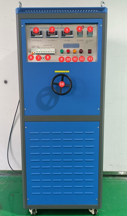
Рисунок 2
Left side and interior of the load cabinet:
① Tungsten filament lamp mounting slots—please install tungsten filament lamps in all 32 slots before use; ② Cooling fan; ③ Power cord for the load cabinet.
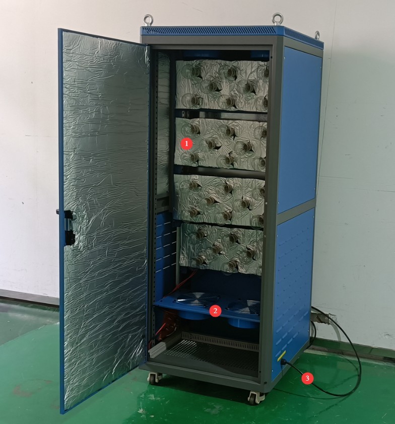
Рисунок 3
Right side of the load cabinet:
① The three terminals on the left are used to connect a separate power supply to power the tungsten filament lamp; ② The four terminals on the right are used to connect to the switch life tester and the test switch.
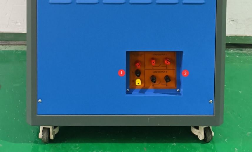
Рисунок 4
1.3.2 Машина для испытаний на долговечность
Испытательные машины выпускаются в двух сериях: трехпозиционные. CZKS-3 и 6-станционный CZKS-6Существует два типа приспособлений: приспособления для проверки розеток и приспособления для проверки выключателей. Рассмотрим CZKS-6 модель в качестве примера:
① Сенсорный экран; ② Выключатель питания; ③ Блок выключателей; ④ Розетка; ⑤ Клеммная колодка; ⑥ Автоматический выключатель; ⑦ Разъем для шнура питания; ⑧ Подключение воздушного компрессора.
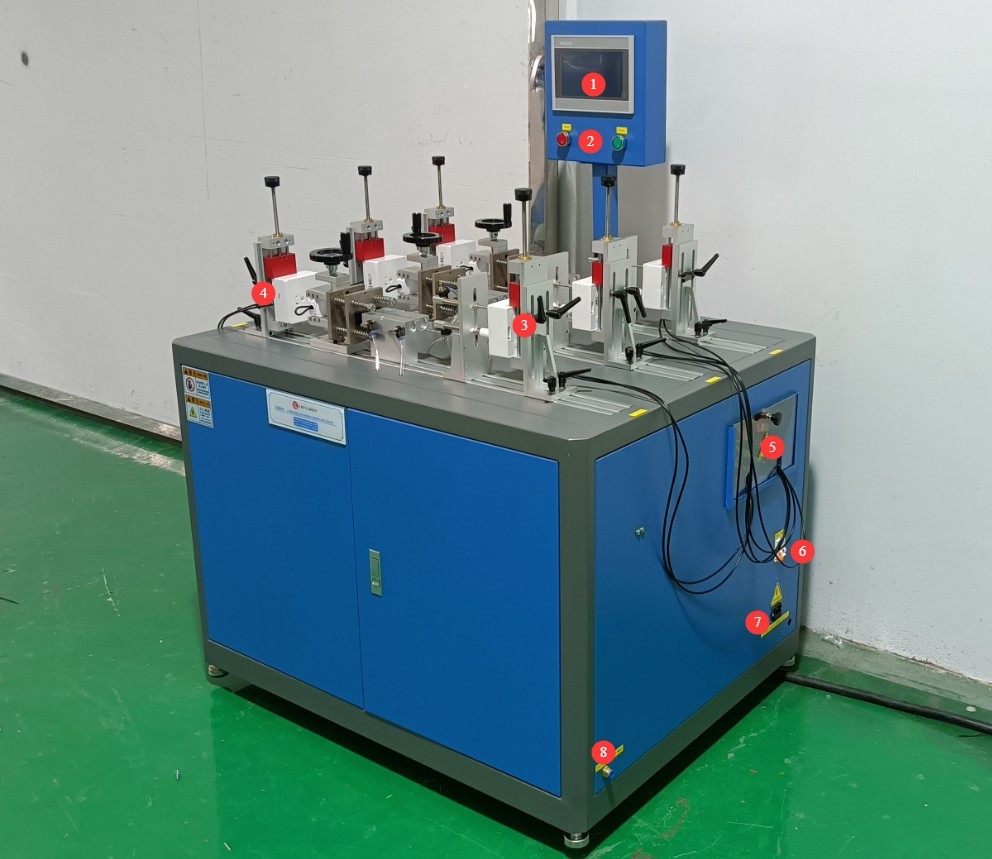
Рисунок 5
2. Меры предосторожности.
2.1 Электробезопасность
2.1.1 Подключение питания
Однофазное питание 220 В; розетки должны соответствовать стандартам безопасности, иметь надлежащее заземление и номинальный ток, соответствующий номинальной мощности оборудования.
Note: The load cabinet itself does not have a high power rating; its maximum current is less than 1 A. However, tungsten filament lamps draw a significant amount of power when in operation. Please check the nameplate and the markings on the terminal blocks, and select a suitable power supply.
2.1.2 Технические характеристики заземления
The equipment must be reliably grounded, with a grounding resistance of ≤4 Ω. Do not use gas pipes, non-metallic water pipes, or neutral wires as substitutes for the grounding wire. After grounding is complete, use a Grounding Resistance Tester to measure the grounding resistance. Power may only be applied after confirming that the requirements are met, to prevent electric shock, equipment malfunctions, or measurement errors caused by poor grounding.
2.2 Эксплуатационная безопасность
Перед подключением проводов, осмотром или техническим обслуживанием оборудования необходимо выключить выключатель питания оборудования и основной источник питания, а также убедиться в отсутствии остаточного напряжения, прежде чем продолжить;
Во избежание поражения электрическим током не следует нажимать на выключатель питания, сенсорный экран или кнопки приборов мокрыми руками;
Не размещайте внутри электрощита посторонние предметы (например, инструменты или бумагу), чтобы предотвратить короткое замыкание или повреждение компонентов из-за пыли или других посторонних предметов;
Не подключайте и не отключайте шнуры питания или сигнальные кабели во время работы оборудования, чтобы предотвратить короткие замыкания, которые могут повредить контроллер или электрические компоненты.
2.3. Экологическая безопасность
Оборудование следует размещать в сухом месте, свободном от коррозионных газов и легковоспламеняющихся или взрывоопасных материалов.
Оборудование должно быть установлено в кондиционированном помещении, при этом температура окружающей среды должна поддерживаться в пределах от 5°C до 35°C, а относительная влажность — ≤ 85%.
Расстояние между оборудованием и стенами, а также окружающими конструкциями (такими как другое испытательное оборудование и стеллажи) должно составлять не менее 1000 мм для облегчения технического обслуживания; перед оборудованием должно быть оставлено не менее 2000 мм пространства для обеспечения бесперебойной работы и отсутствия препятствий в окружающей зоне;
Оборудование необходимо устанавливать на ровной, устойчивой поверхности; высота ножек оборудования регулируется.
Другие 2.4
По вопросам, не охваченным данным руководством, пожалуйста, проявляйте осторожность или свяжитесь с нами.
3. Введение в программу сенсорного экрана для машины для испытания на долговечность.
3.1 Рабочая страница
① Переключение ручного/автоматического режима; ② Тест запуска/остановки; ③ Список станций.
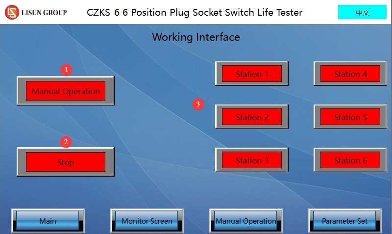
Рисунок 6
3.2 Страница настроек параметров
① Навигация по страницам; ② Общее количество тестов; ③ Время загрузки; ④ Время выключения; ⑤ Количество неудачных попыток мониторинга тока; ⑥ Ведется ли мониторинг тока.
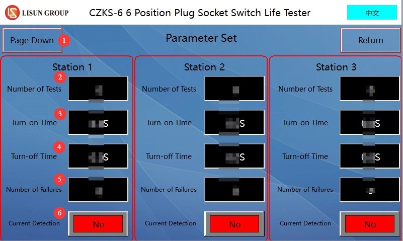
Рисунок 7
Примечание: Пользователи могут устанавливать разные параметры для разных рабочих станций.
3.3 Окно ручного управления
Нажмите кнопку ручного управления для соответствующего рабочего места, чтобы вручную отрегулировать положение приспособления на этом рабочем месте.
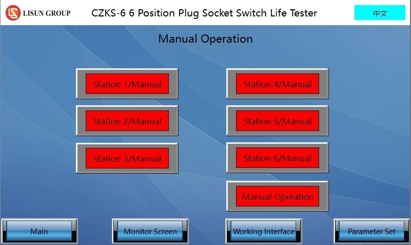
Рисунок 8
3.4 Видеозаписи с камер наблюдения
① Навигация по страницам; ② Запуск/Пауза; ③ Текущий мониторинг; ④ Общее количество тестов; ⑤ Количество выполненных тестов; ⑥ Количество текущих сеансов мониторинга; ⑦ Сброс.
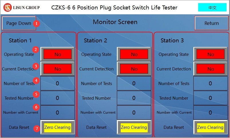
Рисунок 9
4. Подготовка к тесту
4.1 Подключение оборудования
4.1.1 Подключение шнура питания
Please refer to Chapter 2. Turn on the life-cycle tester; do not turn on the load cabinet at this time.
4.1.2 Подключение воздушного компрессора
Connect an air hose with an outer diameter of 8 mm to the endurance testing machine, then turn on the air compressor.
4.1.3 Connecting the Load Cabinet, Endurance Tester, and Specimen
The load cabinet has the following four terminals—two red and two black—as shown in the figure below.
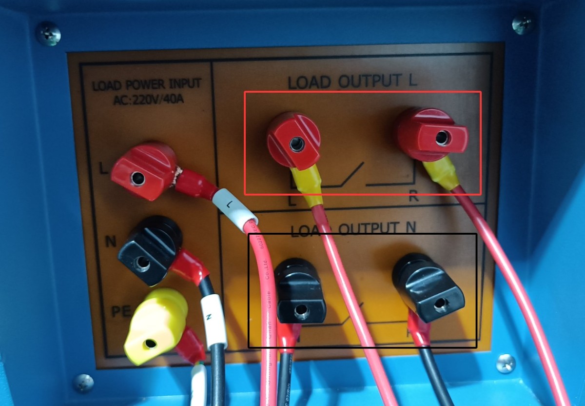
Рисунок 10
4.1.3.1 Single-Pole Switch
Connect the two red terminals or the two black terminals of the load cabinet to the life tester, and then short-circuit the other two terminals.
The two terminals on the load cabinet are connected to terminals A and B on the life testing machine, and terminals A and C on the life testing machine are connected to the sample switch, as shown in the wiring diagram for workstation 4 of the life testing machine below.
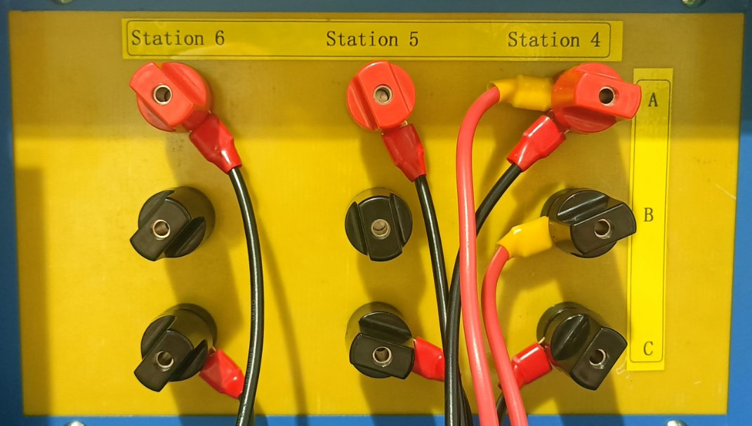
Рисунок 11
4.1.3.2 Dual-Control Switch
Connect the two terminals on the load panel that are short-circuited directly to one circuit of the double-pole switch, and then connect the other circuit of the double-pole switch as described in section 4.1.3.1.
4.2 Пример калибровки
Open the manual window of the life test machine. Click the button for the corresponding test station to perform a single-cycle operation, then observe the position of the machine’s actuators. If the test specimen is a switch, adjust the machine so that when the upper actuator extends, it just closes the switch, and when the lower actuator extends, it just opens the switch.
After debugging is complete, the switch should be set to the off position.
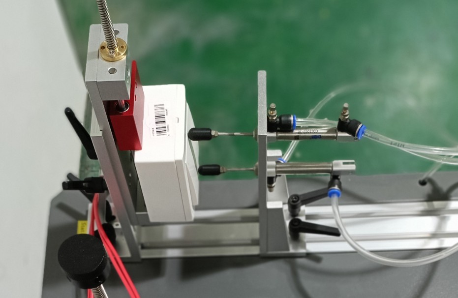
Рисунок 12
5. Switch Life Test Procedure
5.1 Конфигурация шкафа нагрузки
Turn on the power switch for the load cabinet.
The number of test cycles is factory-set to 9999, and the adhesive holding time is factory-set to 90 seconds. Users can also adjust these settings as needed.
Turn on the load cabinet’s power switch, press the “Start Load Output” button, and turn on all cooling fans.
Slowly rotate the voltage adjustment dial while monitoring the test voltage until the voltage meets the test specifications. Note: When the load voltage exceeds 305 V, the device will automatically disconnect the load.
Turn on the tungsten filament lamp quantity selector switch as needed; with a maximum load of 30 tungsten filament lamps (if switches 1, 2, 3, 4, 10, and 10 are all turned on, the total number of tungsten filament lamps in use is 1 + 2 + 3 + 4 + 10 + 10 = 30). Users may also freely combine switches according to their needs.
Example: According to Clause 18.3 of standard GB/T 16915.1-2024 (IEC 60669-1:2017, Clause 18.3), when testing a 10 A, 250 V switch, the voltage required for a 200 W tungsten filament lamp is 240 V, and 15 such lamps are required.
In the manual window of the life test machine, turn on the switch for the corresponding workstation. See the figure below:
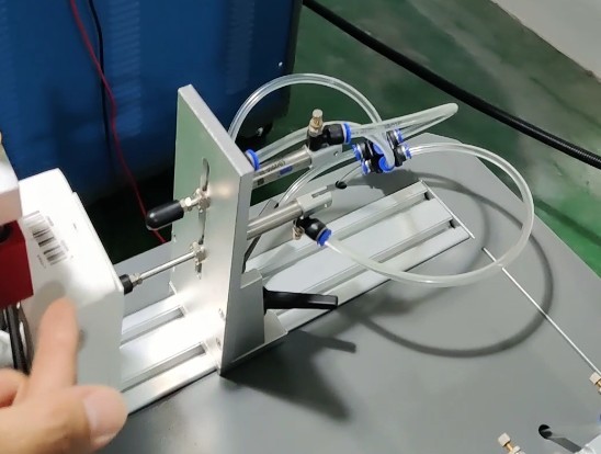
Рисунок 13
After the switch is turned on, the voltage will drop slightly, requiring you to turn the voltage adjustment knob again. At this point, the test load current is 1.2 times the rated current of the sample switch, or approximately 12 A. Note: When the load current exceeds 22 A, the load cabinet will automatically disconnect the load.
Once the adjustment is complete, go to the manual control panel of the endurance tester and return the specimen to its original state by setting the specimen switch to the “OFF” position.
5.2 Настройка машины для испытаний на долговечность
Parameter Settings Interface. For each workstation, configure the total number of tests, load on time, load off time, number of failed current monitoring attempts, and whether to monitor current.
Примечание 1: Количество неисправностей относится к числу случаев, когда образец был запитан, но ток не был обнаружен (тест автоматически остановится, как только фактическое количество неисправностей во время теста достигнет установленного предела; этот параметр недействителен, если мониторинг тока отключен);
Примечание 2: Мониторинг тока следует включать только при подключении к данной испытательной станции нагрузочного шкафа для проведения испытаний.
Monitoring Interface. Used to view the test status and data for the corresponding workstation. Please click the “Reset” button for the corresponding workstation to clear the previous test data before you can begin testing at that workstation.
5.3 Испытание на прочность
5.3.1 Запуск теста
Перейдите в рабочий интерфейс. ① Выберите рабочую станцию, которую хотите запустить, ② нажмите, чтобы переключиться с ручного режима на автоматический, ③ нажмите, чтобы начать тест.
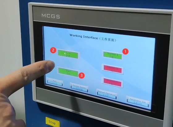
Рисунок 14
5.3.2 Тестовый мониторинг
Во время тестирования вы можете просматривать данные в режиме реального времени на экране мониторинга.
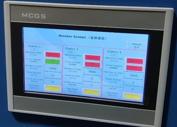
Рисунок 15
5.3.3 Завершение теста
If the number of test cycles at a life test machine station reaches the set limit, that station will stop the test and automatically place the specimen in the disconnected state. Important note: The load cabinet is still outputting power; please turn off the load output before proceeding.
If the life tester station is equipped with selective current monitoring and the number of failures during the test reaches the preset limit, the life tester will automatically stop the test at that station and automatically disconnect the test specimen. Important Note: The load cabinet will still be in the output state; please turn off the load output before proceeding with any further operations.
If a sample at a test station on the life tester is damaged during testing and remains in the “always on” state, the load cabinet will trigger an alarm after the load has been continuously applied for 90 seconds and will automatically cut off the output. Please press the alarm reset button on the front panel of the load cabinet and manually end the test for the corresponding station on the life tester.
6. Процедуры после испытаний
6.1 Просмотр записанных тестовых данных
Получите доступ к экрану мониторинга испытательного стенда, проверьте и запишите данные испытаний для каждой станции.
6.2 Выключение
Выключите воздушный компрессор;
Turn off the life-cycle testing machine;
Disconnect the load output from the load cabinet, turn off the cooling fan, reset the tungsten lamp quantity selector switch to its original position, and turn off the power to the load cabinet.
6.3 Проверка состояния образца
Use a screwdriver to loosen the clamp screws, remove the tested sample, inspect the sample’s appearance (e.g., check for deformation of the socket and plug, or ablation of the switch contacts), and record the test results.
7. Ежедневное техническое обслуживание и уход за оборудованием.
7.1 Чистка и уход
After the test is complete, wipe down the life-test machine fixtures and other components with a dry cloth; do not use corrosive cleaning agents. Remove dust from the equipment’s terminal blocks to prevent poor contact.
7.2 Смазка и техническое обслуживание
Apply lubricating oil to the sliding components of the endurance testing machine (slide rails, cylinder piston rods) to ensure smooth mechanical operation; check the fixture screws and tighten any loose parts promptly.
7.3 Хранение оборудования
7.3.1 Требования к краткосрочному хранению
Если оборудование используется ежедневно, после завершения очистки после каждого теста никаких дополнительных действий не требуется.
7.3.2 Требования к долговременному хранению
Если устройство не будет использоваться в течение длительного периода (более одного месяца), пожалуйста, отсоедините все кабели и накройте устройство пылезащитным чехлом, чтобы предотвратить скопление пыли.
Для предотвращения износа электрических компонентов (таких как конденсаторы и контакторы) устройство следует включать раз в месяц всего на полчаса.
8. Поиск и устранение распространенных проблем
8.1 Failures in Life Testing Machines
8.1.1 Испытательная машина не имеет механического движения.
Causes of malfunction: Insufficient air supply pressure < 0.8 MPa, air leak at the air supply connection, or malfunction of the cylinder solenoid valve;
Решение: отрегулируйте давление в воздушном компрессоре до 0.8 МПа, замените протекающий шланг подачи воздуха и свяжитесь с производителем для ремонта электромагнитного клапана.
8.1.2 Нет изображения на сенсорном экране / Сенсорный экран не реагирует
Причины неисправности: отсутствие подключения питания, ослабленный шлейф сенсорного экрана, ошибка программы ПЛК;
Устранение неполадок: Проверьте подключение питания на тестовом устройстве и надежно подсоедините шлейф сенсорного экрана. В случае программной ошибки обратитесь за помощью к производителю.
8.1.3 Рабочая станция не запускается
Cause of failure: Current monitoring failure, short circuit in the sample wiring, or the number of tests or failures has reached the preset value;
Решение: Проверьте схему подключения, нажмите кнопку «Сброс» на экране мониторинга и замените модуль обнаружения тока, если он поврежден.
8.2. Сбой в работе распределительного щита.
8.2.1 Отсутствие выходного напряжения/тока
Causes of malfunction: Main power not turned on, voltage knob not adjusted, loose terminal connections;
Процедура: Включите основной источник питания нагрузочного шкафа, установите регулятор напряжения на номинальное значение и затяните винты клемм.
8.2.2 Ненормальное отображение в таблице электрических параметров
Causes of malfunction: Corrupted parameter table, stuck voltage dial, poor sample contact;
Решение: Замените измеритель электрических параметров, удалите мусор с поворотного стола и установите образец на место, чтобы обеспечить надлежащий контакт.
8.2.3 Непрерывная сигнализация оборудования
Causes of malfunction: Sample current remains active for more than 90 seconds, load overload, or a malfunctioning alarm reset button;
Troubleshooting: Check for a short circuit in the sample, reduce the load current to the rated value, and replace the alarm reset button.
8.3 Совместные отказы при испытаниях
Failure Symptom: Frequent failures of test specimens during electrical life testing
Причина неисправности: параметры нагрузки не соответствуют стандартным требованиям; отклонение в положении образца при установке;
Solution: Readjust the current and power factor of the load cabinet to the standard values, and adjust the mechanical position of the testing machine to ensure good contact with the sample.