
 Английский
 中文简体
中文简体 Русский
 Español
 Português
 Türkçe
 العربية
 Deutsch
 Polski
 Italiano
 Français
 한국어
한국어 ไทย
ไทย Tiếng Việt
 日本語
日本語





























Измеритель ресурса выключателей и розеток в шкафу управления.
Руководство пользователя
Применимый LISUN модели: CZKS-3,CZKS-3А.CZKS-3P、CZKS-3S、CZKS-6,CZKS-6P、CZKS-6S、CZKS-6X、DFX-20,DFX-20-3CH、DFX-40、DFX-60、DFX-80
1. Распаковка и базовое ознакомление с оборудованием.
1.1 Основные технические характеристики
1.1.1 DFX Series Load Cabinets
| LISUN Модель | DFX-20 | DFX-20-3CH | ДФС-40 | ДФС-60 | ДФС-80 |
| Диапазон выходного тока | 0–20 А на канал | 0-40 A | 0-60 A | 0-80 A | |
| Точность выходного тока | 0.1 | ||||
| Количество выходных каналов | Одноканальный выход | Three-Channel Output | Одноканальный выход | ||
| Электропитание | 220 В переменного тока/50 Гц/40 А | 220 В переменного тока/50 Гц/100 А | 220 В переменного тока/50 Гц/80 А | 220 В переменного тока/50 Гц/120 А | 220 В переменного тока, 50 Гц, 160 A |
1.1.2 CZKS Series Socket and Switch Life Test Machine
| LISUN Модель | CZKS-3 | CZKS-3P | CZKS-3S | CZKS-3A |
| Рабочая станция | 2 Outlets + 1 Switch | 3-outlet outlet | Переключатели 3 | 1 Outlet + 2 Switches |
| Тип привода | Pneumatic drive; customer must provide air supply: 0.8 MPa | |||
| Метод управления | PLC + Extra-Large Touchscreen | |||
| Время включения/выключения | 0–99.9 seconds per minute (adjustable) | |||
| Количество тестов | 0–999999 times (preset) | |||
| Тестирование | Linear: -40 to 110 mm (preset); Rotation: 0 to 360° (preset) | |||
| Скорость тестирования | Linear: 0–100 mm/s (preset); Rotational: 0–90°/s (preset) | |||
| Образец приспособления | Comes standard with a universal clamp that can be adjusted up and down (other special configurations can be custom-made upon customer request) | |||
| LISUN Модель | CZKS-6 | CZKS-6P | CZKS-6S | CZKS-6X |
| Рабочая станция | 3 Outlets + 3 Switches | 6-outlet outlet | Переключатели 6 | Custom Number of Outlets + Switches |
| Тип привода | Pneumatic cylinder drive; customer must provide air supply: 0.8 MPa | |||
| Методы контроля | PLC + Extra-Large Touchscreen | |||
| Время включения/выключения | 0–99.9 seconds per minute (adjustable) | |||
| Количество тестов | 0–999999 times (preset) | |||
| Тестирование | Linear: -40 to 110 mm (preset); Rotation: 0 to 360° (preset) | |||
| Скорость тестирования | Linear: 0–100 mm/s (preset); Rotational: 0–90°/s (preset) | |||
| Образец приспособления | Comes standard with universal clamps that are height-adjustable (other special configurations can be custom-made upon customer request) | |||
1.2 Распаковка, осмотр и проверка аксессуаров
1.2.1 Распаковка и визуальный осмотр
При распаковке устройства обращайтесь с ним осторожно, чтобы не поцарапать корпус острыми предметами. После распаковки сначала осмотрите внешний вид устройства, чтобы убедиться в отсутствии видимых деформаций или вмятин, а также в том, что кнопки не повреждены и не расшатаны.
Если вы обнаружите какие-либо повреждения или деформации оборудования или принадлежностей, не включайте питание. Немедленно свяжитесь с нами.
1.2.2 Основной блок и принадлежности
Load cabinet: 1 unit; Socket and switch life tester: 1 unit.
Note 1: The life tester requires a compressed air compressor to operate properly. Users may purchase one from LISUN or provide their own. If providing your own, please ensure it is capable of delivering compressed air at 0.8 MPa. An air hose with an 8 mm outer diameter is required for connection to the life tester.
Note 2: According to the standard, the socket service life test requires the use of specially manufactured standard plugs, which users can purchase from LISUN or provide themselves.
Ссылки для скачивания цифрового руководства пользователя, гарантийного талона и других документов были отправлены вам по электронной почте. Пожалуйста, скачайте их как можно скорее. Если вы пропустили письмо, пожалуйста, свяжитесь с нами, чтобы получить ссылки для скачивания повторно.
1.3 Описание конструкции оборудования
1.3.1 Load Cabinet
Single-bay load cabinet:
① Power cord; ② Connection cable between the load cabinet and the life tester; ③ Electrical parameter meter, displaying load voltage, current, and power factor;④ Power switch; ⑤ Load output switch; ⑥ Long-stick protection timer—if the load cabinet’s continuous output exceeds the set long-stick protection time, an alarm will sound and the output will automatically shut off; the factory default is 90 seconds, and no modification is required;⑦ Alarm reset; ⑧ Load on/off indicator light; ⑨ Alarm; ⑩ Load type selector switch; ⑪ Load voltage adjustment; ⑫ Load current adjustment; ⑬ Load power factor adjustment.
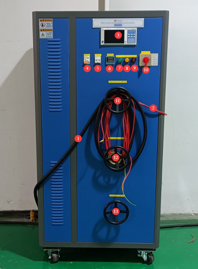
Рисунок 1
Multi-station load cabinet:
① Load voltage display; ② Load voltage adjustment—multiple workstations use the same load voltage; ③ Main power switch;
Description of the Load Cabinet Workstation Structure:
④ Current display; ⑤ Power factor display; ⑥ Load cabinet switch; ⑦ Load output switch; ⑧ Alarm reset; ⑨ Load on/off indicator light; ⑩ Alarm; ⑪ Load type selector switch; ⑫ Load current adjustment; ⑬ Load power factor adjustment.
The structures of the other stations (14 and 15) in the load cabinet are identical.
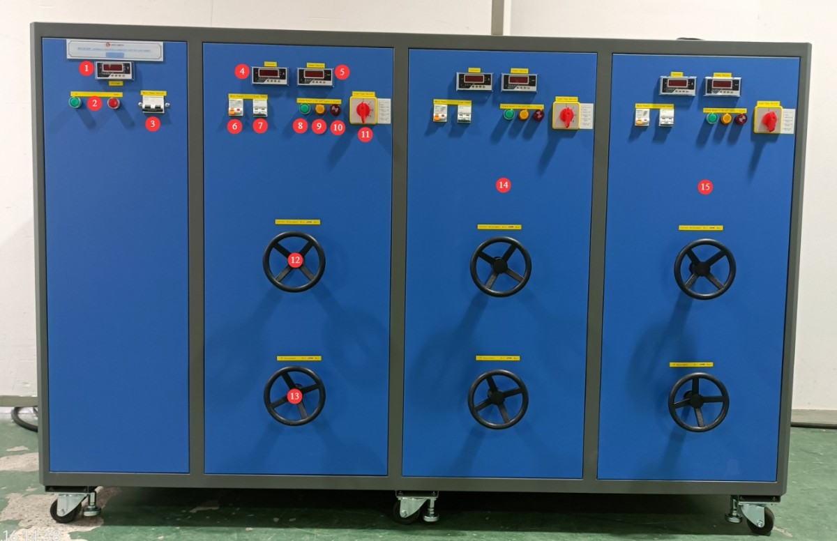
Рисунок 2
1.3.2 Life Test Machine
The life test machines are available in two series: the 3-station CZKS-3 and the 6-station CZKS-6. There are two types of fixtures: fixtures for testing sockets and fixtures for testing switches. Taking the CZKS-6 model as an example:
① Touchscreen; ② Power switch; ③ Switch fixture; ④ Outlet fixture; ⑤ Terminal block; ⑥ Circuit breaker; ⑦ Power cord receptacle; ⑧ Air compressor connection.
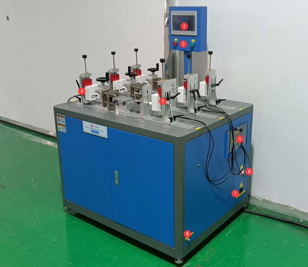
Рисунок 3
2. Меры предосторожности.
2.1 Электробезопасность
2.1.1 Подключение питания
220V single-phase power. Power outlets must comply with safety standards, have proper grounding, and have a rated current that matches the equipment’s power rating. Important note: Since the load cabinet has a high power rating, please check the nameplate to ensure you are using a suitable power source.
2.1.2 Технические характеристики заземления
The equipment must be reliably grounded, with a grounding resistance of ≤4 Ω. Do not use gas pipes, non-metallic water pipes, or neutral wires as substitutes for the grounding wire. After grounding is complete, use a Grounding Resistance Tester to measure the grounding resistance. Power may only be turned on after confirming that the resistance meets the requirements, to prevent electric shock, equipment malfunctions, or measurement errors caused by poor grounding.
2.2 Эксплуатационная безопасность
Перед подключением проводов, осмотром или техническим обслуживанием оборудования необходимо выключить выключатель питания оборудования и основной источник питания, а также убедиться в отсутствии остаточного напряжения, прежде чем продолжить;
Во избежание поражения электрическим током не следует нажимать на выключатель питания, сенсорный экран или кнопки приборов мокрыми руками;
Не размещайте внутри электрощита посторонние предметы (например, инструменты или бумагу), чтобы предотвратить короткое замыкание или повреждение компонентов из-за пыли или других посторонних предметов;
Do not plug in or unplug power or signal cables while the equipment is running, to prevent short circuits that could damage the controller or electrical components.
2.3. Экологическая безопасность
The equipment should be placed in a dry environment free of corrosive gases and flammable or explosive substances.
The equipment must be installed in an air-conditioned room, with the ambient temperature maintained between 5°C and 35°C and relative humidity at 85% or less.
The equipment must be placed at least 1000 mm away from walls and surrounding structures (such as other testing equipment and shelves) to facilitate maintenance; a space of at least 2000 mm must be left in front of the equipment to ensure smooth operation and to keep the surrounding area free of obstructions.
Оборудование необходимо устанавливать на ровной, устойчивой поверхности; высота ножек оборудования регулируется.
Другие 2.4
По вопросам, не охваченным данным руководством, пожалуйста, проявляйте осторожность или свяжитесь с нами.
3. Introduction to the Touchscreen Program for the Life Test Machine
3.1 Work Page
① Manual/Automatic Switch; ② Start/Stop Test; ③ Station List.
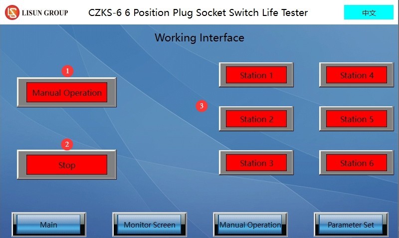
Рисунок 10
3.2 Страница настроек параметров
① Page navigation; ② Total number of tests; ③ Load on time; ④ Load off time; ⑤ Number of failed current monitoring attempts; ⑥ Whether current is being monitored.
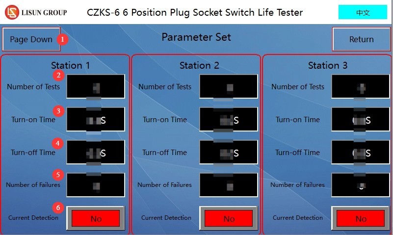
Рисунок 11
Note: Users can set different parameters for different workstations.
3.3 Окно ручного управления
Click the manual control button for the corresponding workstation to manually adjust the position of the fixture at that workstation.
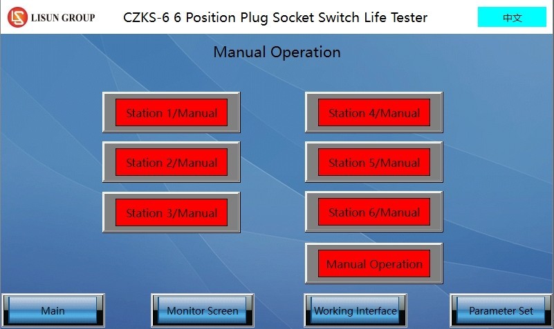
Рисунок 12
3.4 Surveillance Footage
① Page navigation; ② Run/Pause; ③ Monitor current; ④ Total number of tests; ⑤ Number of tests performed; ⑥ Number of current monitoring sessions; ⑦ Reset.
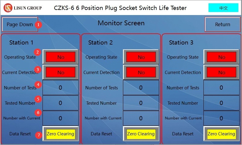
Рисунок 13
4. Подготовка к тесту
4.1 Подключение оборудования
4.1.1 Подключение шнура питания
Please refer to Chapter 2 to turn on the life-cycle tester; do not turn on the load cabinet at this time.
4.1.2 Air Compressor Connection
Connect an air hose with an outer diameter of 8 mm to the endurance tester, and turn on the air compressor.
4.1.3 Connecting the Load Cabinet and the Life Tester to the Specimen
4.1.3.1 If the sample is a switch
Short-circuit the two red terminals on the load cabinet, and connect the two black terminals, A and B, to the life tester.
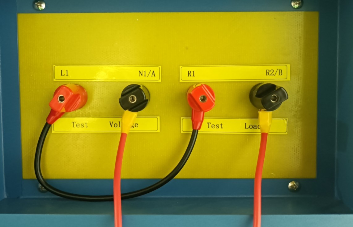
Рисунок 4
Terminals A and B of the load cabinet are connected to terminals A and B of the life tester, and terminals A and C of the life tester are connected to the sample switch, as shown in the wiring diagram for workstation 4 of the life tester in the figure below.
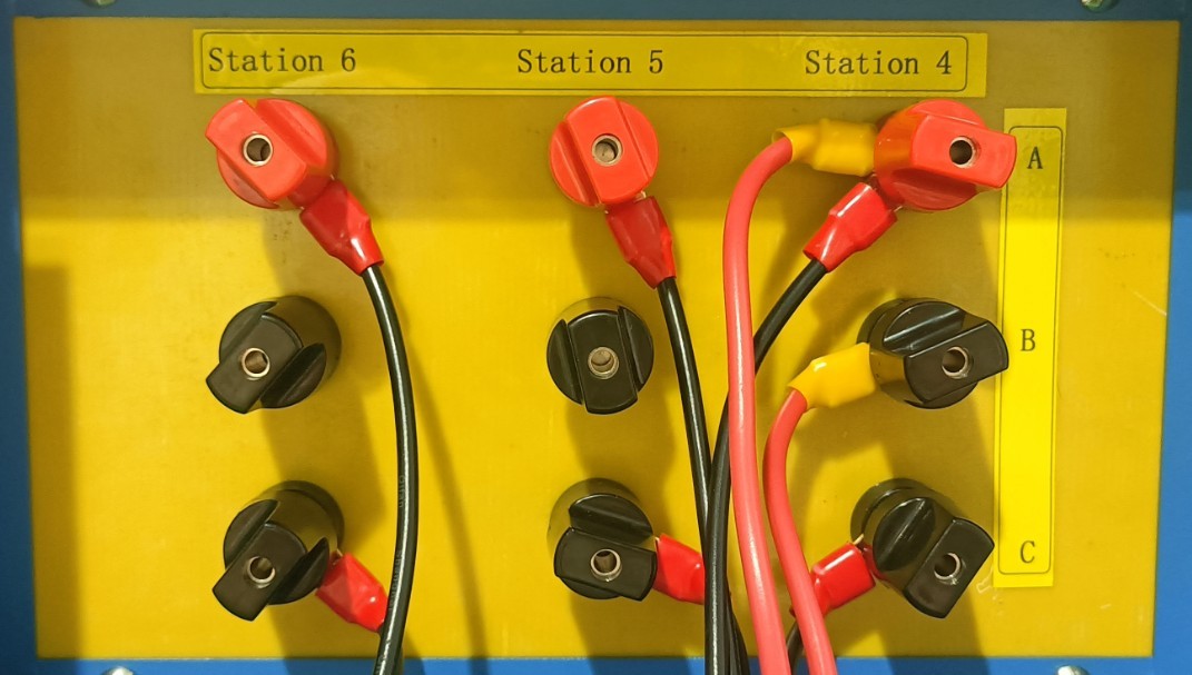
Рисунок 5
On the life-test machine, terminals A and C are connected to the sample switch, as shown in the figure below.
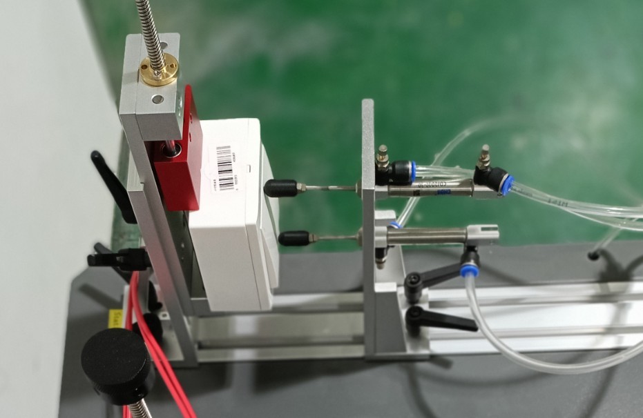
Рисунок 6
4.1.3.2 If the sample is a receptacle
Connect the L1 and N1 terminals of the load cabinet to the life tester, and connect the R1 and R2 terminals to the corresponding standard plugs.
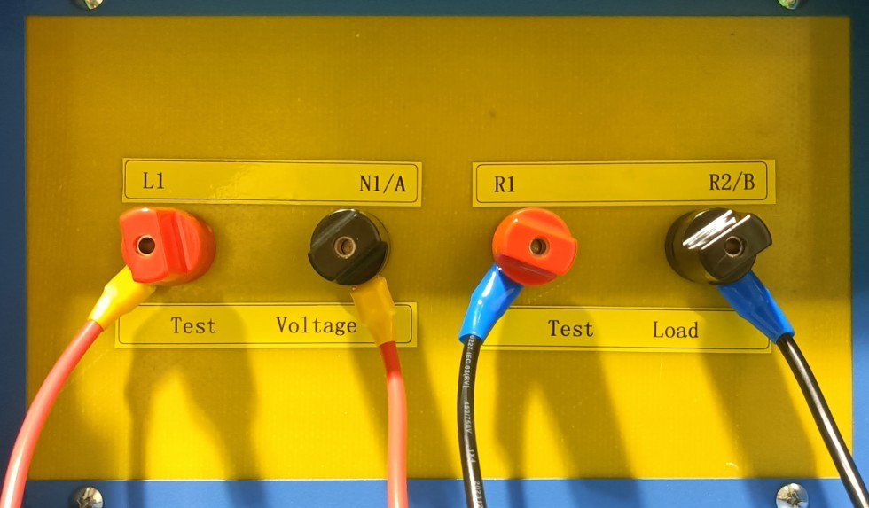
Рисунок 7
Connect the L1 and N1 terminals of the load cabinet to the L1 and N1 terminals of the life tester, and connect the A/L1 and C terminals of the life tester to the test specimen socket, as shown in the wiring diagram for Workstation 1 of the life tester.
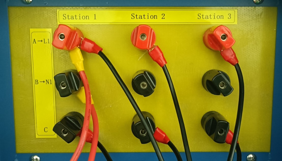
Рисунок 8
Connect the two terminals, R1 and R2, on the load cabinet to the corresponding standard plugs, as shown in the figure below.
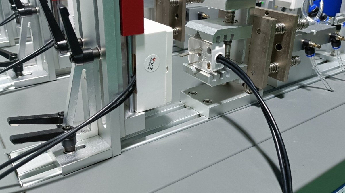
Рисунок 9
4.2 Sample Calibration
Open the manual window of the life test machine. Click the corresponding station button to perform a single-cycle operation, then observe the position of the test machine’s actuator rods. If the sample is a switch, adjust the machine so that when the upper actuator rod extends, it just closes the switch, and when the lower actuator rod extends, it just opens the switch. See the figure below:
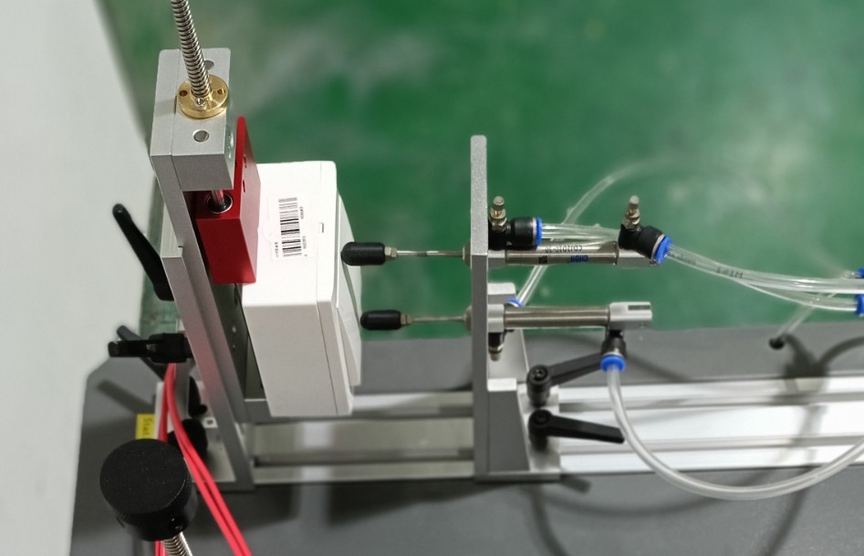
Рисунок 14
If the sample is a socket, adjust it so that the left and right parts are as close together as possible when the plug is inserted into the socket. See the figure below:
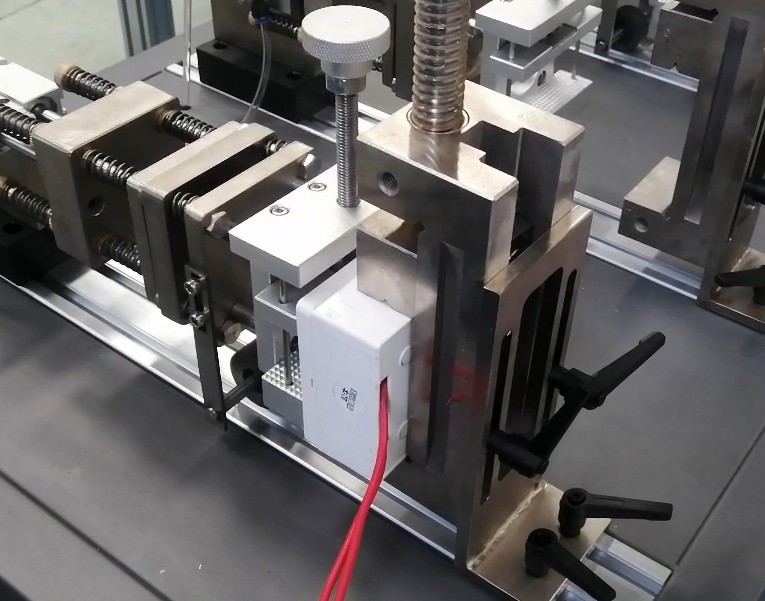
Рисунок 15
After debugging is complete, set the switch to the “off” position and disconnect the plug from the outlet.
5. Life Test Procedures
5.1 Конфигурация шкафа нагрузки
Turn on the load cabinet. Set the load type switch to the required setting according to the sample and standard requirements.
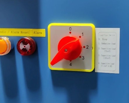
Рисунок 16
The single-station load cabinet uses an electrical parameter display to show voltage, current, and power factor. The first row displays voltage, the second row displays current, and pressing the button shown in the figure below switches the third row to display the power factor (PF).
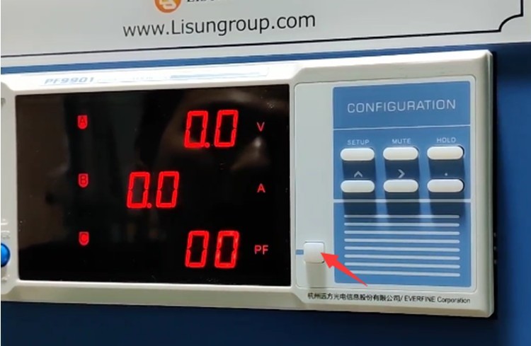
Рисунок 17
Turn on the load output. Adjust the output voltage of the load cabinet (Note: The display for adjusting the load voltage and load parameters differs between single-station and multi-station load cabinets; please refer to Section 1.3.1). Set the load cabinet’s output voltage to the desired value.
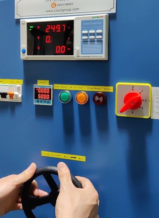
Рисунок 18
Adjust the current and power factor. First, turn both the current and power factor dials to their minimum positions. Then, in the manual window of the life tester, turn on the switch for the corresponding station or plug the power cord into the outlet. See the figure below:
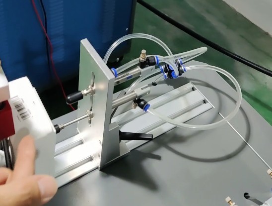
Рисунок 19
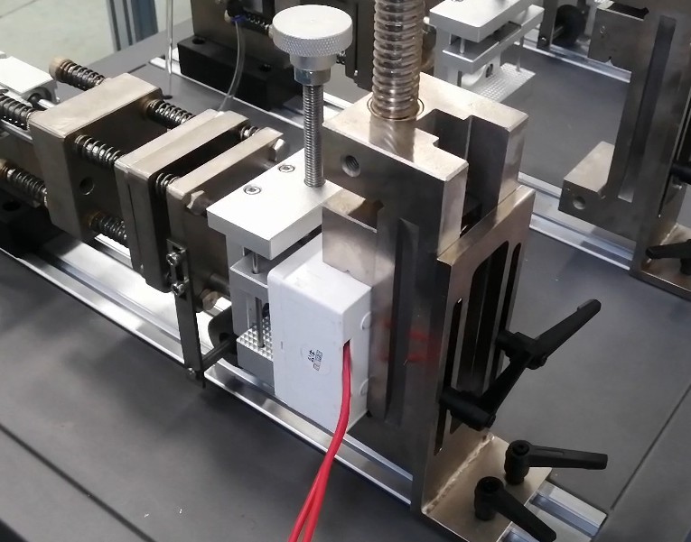
Рисунок 20
The load cabinet’s electrical parameter display will then show the current and power factor of the sample when the load is energized. Note: Current and power factor affect each other; you must adjust the current and power factor dials simultaneously and gradually. Note: If adjustment is not successful within 90 seconds, the load cabinet will sound an alarm. Press the alarm reset button on the front panel of the load cabinet to continue debugging.
Once the settings are adjusted, go to the manual interface of the endurance testing machine and return the sample to its original state.
5.2 Setting Up the Life Test Machine
Parameter Settings Interface. For each workstation, configure the total number of tests, load on time, load off time, number of current monitoring failures, and whether to monitor current.
Note 1: The number of faults refers to the number of times the sample was energized but no current was detected (the test will automatically stop once the actual number of faults during the test reaches the set fault limit; this parameter is invalid when current monitoring is disabled);
Note 2: Current monitoring should only be enabled when a load cabinet is connected to that test station for testing.
Monitoring Interface. Used to view the test status and data for the corresponding workstation. Please click the “Reset” button for the corresponding workstation to clear the previous test data before starting the test for that workstation.
5.3 Life Test
5.3.1 Запуск теста
Go to the work interface. ① Select the workstation you want to run, ② click to switch from manual to automatic, ③ click to start the test.
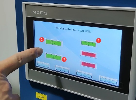
Рисунок 21
5.3.2 Тестовый мониторинг
During the test, you can view real-time data on the monitoring screen.
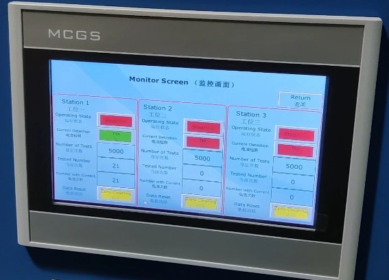
Рисунок 22
5.3.3 Завершение теста
If the number of test cycles at a life test machine station reaches the set limit, that station will stop the test and automatically place the sample in the “disconnected” state. Important note: The load cabinet is still outputting power; please turn off the load output before proceeding.
If the life tester station is equipped with selective current monitoring and the number of faults during the test reaches the preset limit, the life tester will automatically stop the test at that station and automatically disconnect the test specimen. Important Note: The load cabinet is still in the output state; please turn off the load output before proceeding.
If a sample at a test station on the life tester is damaged during testing and remains in the “always on” state, the load cabinet will trigger an alarm after the load has been continuously applied for 90 seconds and will automatically cut off the output. Please press the alarm reset button on the front panel of the load cabinet and manually end the test for the corresponding test station on the life tester.
6. Процедуры после испытаний
6.1 Viewing Recorded Test Data
Access the life test machine monitoring screen, check and record the test data for each station.
НИКОГДА не выключаться
Turn off the air compressor;
Turn off the life-cycle testing device;
Set the voltage, current, and power factor of the load cabinet to their lowest settings, turn off the load cabinet’s load output, and turn off the load cabinet’s power supply.
6.3 Check the Sample Condition
Use a screwdriver to loosen the clamp screws, remove the tested sample, inspect its appearance (e.g., check for deformation of the socket and plug, or ablation of the switch contacts), and record the test results.
7. Ежедневное техническое обслуживание и уход за оборудованием.
7.1 Чистка и уход
After the test is complete, wipe down the life test machine fixtures and other components with a dry cloth; do not use corrosive cleaning agents. Remove dust from the equipment’s terminal blocks to prevent poor contact.
7.2 Смазка и техническое обслуживание
Apply lubricating oil to the sliding components of the life-cycle testing machine (slide rails, cylinder piston rods) to ensure smooth mechanical operation; check the fixture screws and tighten any loose parts promptly.
7.3 Хранение оборудования
7.3.1 Требования к краткосрочному хранению
Если оборудование используется ежедневно, после завершения каждого теста и очистки оборудования никаких дополнительных действий не требуется.
7.3.2 Требования к долговременному хранению
Если устройство не будет использоваться в течение длительного периода (более одного месяца), пожалуйста, отсоедините все кабели и накройте устройство пылезащитным чехлом, чтобы предотвратить скопление пыли.
Для предотвращения износа электрических компонентов (таких как конденсаторы и контакторы) устройство следует включать один раз в месяц всего на полчаса.
8. Поиск и устранение распространенных проблем
8.1 Failures in Life Test Machines
8.1.1 The testing machine has no mechanical movement
Causes of Failure: Insufficient air supply pressure (<0.8 MPa), air leak at the air supply connection, or malfunction of the cylinder solenoid valve;
Solution: Adjust the air compressor pressure to 0.8 MPa, replace the leaking air supply hose, and contact the manufacturer to repair the solenoid valve.
8.1.2 No Display on the Touchscreen / Touchscreen Not Responding
Causes of the malfunction: Power not connected, loose touchscreen ribbon cable, PLC program error;
Troubleshooting: Check the power connections on the testing machine and firmly reconnect the touchscreen ribbon cable. If there is a software error, contact the manufacturer for assistance.
8.1.3 The Workstation Fails to Start
Cause of failure: Current monitoring failure, short circuit in the sample wiring, or the number of tests or failures has reached the set value;
Solution: Check the sample wiring, click the “Reset” button on the monitoring screen, and replace the current detection module if it is damaged.
8.2 Load Cabinet Failure
8.2.1 No Voltage/Current Output
Causes of malfunction: Main power is not turned on; voltage knob is not adjusted; loose terminals;
Procedure: Turn on the main power supply to the load cabinet, adjust the voltage knob to the rated value, and tighten the terminal screws.
8.2.2 Abnormal Display in the Electrical Parameters Table
Causes of failure: Corrupted parameter table, stuck current/power factor dial, poor sample contact;
Solution: Replace the electrical parameter meter, remove any debris from the turntable, and reinstall the sample to ensure proper contact.
8.2.3 Continuous Equipment Alarms
Causes of malfunction: Sample current remains on for more than 90 seconds, load overload, or a malfunctioning alarm reset button;
Troubleshooting: Check the sample for short circuits, reduce the load current to the rated value, and replace the alarm reset button.
8.3 Joint Test Failures
Failure Symptom: Frequent failures of test samples during electrical endurance testing
Cause of the malfunction: Load parameters do not meet standard requirements; deviation in the sample installation position;
Solution: Readjust the current/power factor of the load cabinet to the standard values, and adjust the mechanical position of the testing machine to ensure good contact with the sample.