
 Английский
 中文简体
中文简体 Русский
 Español
 Português
 Türkçe
 العربية
 Deutsch
 Polski
 Italiano
 Français
 한국어
한국어 ไทย
ไทย Tiếng Việt
 日本語
日本語





























Испытание иглы на пламя
Руководство пользователя
Применимый LISUN модели: ZY-3,ZY-3S
1. Распаковка и базовое ознакомление с оборудованием.
1.1 Основные технические характеристики
| LISUN Модель | ZY-3 | ZY-3S |
| Наименование | С жильем | Без чехла |
| Угол наклона горелки | Adjustable; tilted at 45° during testing; vertical during flame height calibration | |
| Горючий газ | ≥95% бутана (опционально электронный расходомер газа) | |
| Диапазон измерения температуры | 0-1000 ° C | |
| Requirements for Increasing Flame Temperature | Heated from 100°C ± 2°C to 700°C ± 3°C in 23.5 s ± 1 s | |
| Thermocouples for Temperature Measurement | Φ0.5 mm Type K | |
| Number of Ignition Attempts per Test | Can be set for single or multiple consecutive ignitions | |
| Материал корпуса | Стальные конструкции с высокотемпературным напылением обладают термостойкостью и коррозионной стойкостью, что делает их пригодными для длительных испытаний в условиях высоких температур. | |
| Дисплей работы | Фирменный сверхбольшой ЖК-сенсорный экран + четкие индикаторные лампочки + дистанционное управление | |
| Вес | Вес брутто 180 кг | Вес брутто 40 кг |
1.2 Распаковка, осмотр и проверка аксессуаров
1.2.1 Распаковка и визуальный осмотр
When unpacking the equipment, handle it gently to avoid scratching the exterior casing with sharp tools. After unpacking, first inspect the exterior of the main unit to ensure there is no visible deformation, dents, or peeling paint, and that the panel gauges and buttons are not damaged or loose. If you find any damage or deformation to the equipment or its accessories, do not power it on for use.
Откройте дверцу испытательной камеры и проверьте, не отсоединились ли какие-либо внутренние компоненты во время транспортировки или не обнаружены ли какие-либо другие неисправности.
If you notice anything unusual, please contact us promptly.
1.2.2 Основной блок и принадлежности
Needle Flame Test Main Unit: 1 unit.
Standard accessories include: ① Exhaust pipe, ② Copper block and thermocouple, ③ Silk paper, ④ Remote control, ⑤ Gauge, ⑥ Sample tray, ⑦ Igniter, ⑧ Stainless steel hose clamp (for securing the exhaust pipe), ⑨ Spare needles, spare fuses;⑩ Power cord, ⑪ Gas supply unit, ⑫ Butane gas.
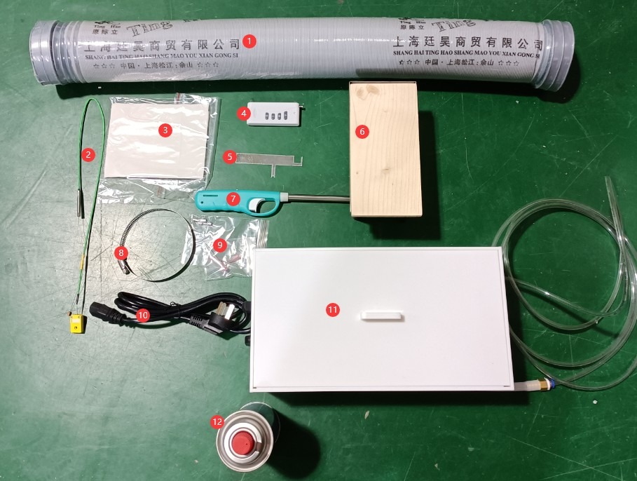
Рисунок 1
Note: Butane gas and batteries are classified as hazardous materials and may not be shipped with the product. Please purchase compliant gas on your own for testing purposes. If you need to use a remote control, please also purchase batteries specifically designed for the remote control.
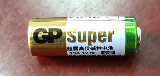
Рисунок 2
Пульт дистанционного управления выполняет те же функции, что и сенсорные кнопки; пользователи могут выбрать, использовать пульт или нет.
Note: Download links for the electronic user manual, warranty card, and other documents have been sent via email. Please download them promptly. If you missed the email, you may contact us directly to request the download links again.
1.3 Описание конструкции оборудования
1.3.1 Вид спереди испытательной камеры
① Touchscreen; ② Power controls, circuit breaker, and power on/off buttons; ③ Butane gas flow meter; ④ Test chamber door.
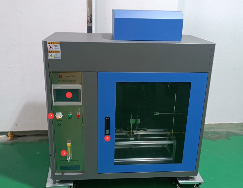
Рисунок 3
1.3.2 Задняя часть испытательной камеры
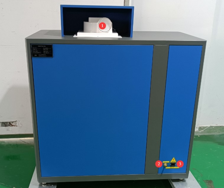
Рисунок 4
① Exhaust vent, 100 mm in diameter, securely connected to an exhaust pipe that extends to the outdoors; ② Butane inlet; ③ Power cord receptacle.
1.3.3 Внутри испытательной камеры
① Needle-flame burner, with adjustable height and angle; ② Sample holder, with adjustable position to meet different testing requirements; ③ Omega Type K thermocouple connector; ④ Thermocouple compensation lead.
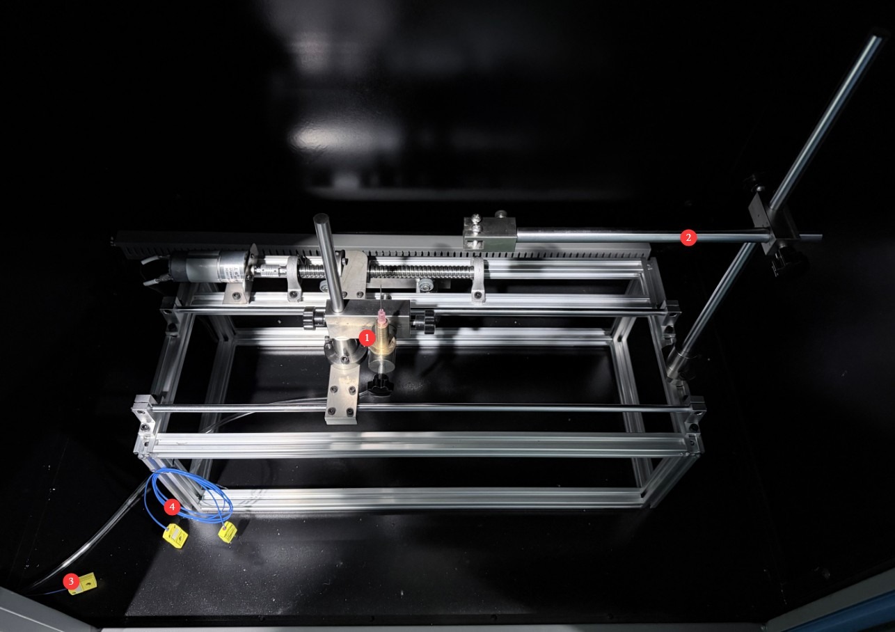
Рисунок 5
Note: These are required when measuring the temperature rise in steps ③ and ④.
2. Меры предосторожности.
2.1 Электробезопасность
2.1.1 Подключение питания
Однофазное питание 220 В; розетки должны соответствовать стандартам безопасности, обеспечивать надлежащее заземление и иметь номинальный ток, соответствующий номинальной мощности оборудования (рекомендуется установить отдельный автоматический выключатель).
2.1.2 Технические характеристики заземления
The equipment must be reliably grounded, with a grounding resistance of ≤4 Ω. Do not use gas lines, non-metallic water pipes, or neutral wires as substitutes for the grounding wire. After grounding is complete, use a Grounding Resistance Tester to measure the grounding resistance. Power may only be applied after confirming that the resistance meets the requirements, to prevent electric shock, equipment malfunction, or measurement errors caused by poor grounding.
2.1.3 Противопоказания к проведению процедуры
Before wiring, inspecting, or maintaining equipment, the main power supply to the equipment must be disconnected, and operation may only begin after confirming that there is no residual voltage;
Во избежание поражения электрическим током не следует нажимать на выключатель питания, сенсорный экран или кнопки приборов мокрыми руками;
Не размещайте внутри электрощита посторонние предметы (например, инструменты или бумагу), чтобы предотвратить короткое замыкание или повреждение компонентов из-за пыли или других посторонних предметов;
Не подключайте и не отключайте шнуры питания или сигнальные кабели во время работы оборудования, чтобы предотвратить короткие замыкания, которые могут повредить контроллер или электрические компоненты.
2.2 Эксплуатационная безопасность
2.2.1 Эксплуатационная безопасность
Во время работы оборудования лицам, не являющимся специалистами, запрещается его разборка или ремонт. В случае неисправности следует обратиться к сотрудникам сервисной службы или эксплуатировать оборудование под руководством специалиста.
Во время испытаний дверца высокотемпературной камеры должна быть закрыта. Наблюдайте за процессом испытаний через смотровое окно камеры, чтобы избежать ожогов от высокотемпературного излучения или искр от горящих материалов.
In the event of a malfunction or abnormality, immediately stop the test and troubleshoot the problem (see “Chapter 9: Troubleshooting and Handling Common Malfunctions”). Do not force the equipment to start up; operating the equipment before the problem is resolved may cause further damage to the equipment.
2.2.2 Запрещенное поведение
Do not use butane gas with a purity lower than 95% to avoid affecting flame stability and test accuracy;
Не открывайте дверцу шкафа управления во время работы оборудования, чтобы избежать прикосновения к внутренним высоковольтным компонентам и поражения электрическим током;
Не разбирайте основные компоненты без разрешения; модификация оборудования аннулирует гарантию и может привести к инцидентам, связанным с безопасностью;
Do not place heavy objects (such as tools or accessories) on top of the equipment to avoid damaging the equipment panel or impeding heat dissipation;
Не складывайте вокруг оборудования легковоспламеняющиеся предметы (например, картонные коробки, полиэтиленовую пленку и т. д.).
2.3. Экологическая безопасность
2.3.1 Требования к установке
Оборудование должно быть установлено в кондиционированном помещении, где температура окружающей среды поддерживается в пределах от 5°C до 25°C, а относительная влажность составляет ≤85%. При высокой влажности окружающей среды вблизи дверцы оборудования и тестовых портов может образовываться конденсат; в таких случаях следует улучшить вентиляцию помещения или использовать осушитель воздуха.
Место установки должно быть свободно от высокой концентрации пыли, коррозионных газов (таких как диоксид серы и хлор), а также легковоспламеняющихся или взрывоопасных атмосфер. Не допускайте попадания прямых солнечных лучей на оборудование, чтобы предотвратить коррозию корпуса и износ электрических компонентов.
Хранение легковоспламеняющихся и взрывоопасных материалов (таких как спирт, бензин и т. д.) в зоне испытаний строго запрещено во избежание риска пожара или взрыва;
Butane gas is a highly flammable substance. Store it at a temperature of ≤40°C, and keep it away from direct sunlight, violent impacts, and sources of fire;
The work area is equipped with fire extinguishers (dry powder or carbon dioxide types), and operators are familiar with how to use them;
Keep the equipment away from areas with significant fluctuations in ambient temperature, such as near ventilation ducts and room entrances, to prevent these fluctuations from affecting the equipment’s temperature control accuracy;
Избегайте источников сильных магнитных и электрических помех (таких как крупные электродвигатели и высоковольтное оборудование).
2.3.2 Требования к пространству
The distance between the equipment enclosure and the wall, as well as surrounding structures (such as other test equipment and shelving), must be at least 1000 mm to facilitate maintenance;
Для обеспечения возможности открывания двери в любом направлении и облегчения размещения и извлечения образцов необходимо оставить зазор не менее 2000 мм у дверцы оборудования.
2.3.3 Горизонтальное размещение
Устройство необходимо установить на ровной поверхности. Используйте уровень, чтобы убедиться, что устройство установлено ровно: поместите уровень на верхнюю поверхность устройства и убедитесь, что пузырек находится по центру. Примечание: устройство имеет четыре регулируемые ножки, которые можно использовать для выравнивания. После выравнивания убедитесь, что все четыре ножки плотно прилегают к поверхности.
If the equipment is tilted, it will cause the needle flame burner to be misaligned and may result in the displacement of the sample, burner, temperature-rising copper block, and other components, thereby affecting the test results.
Другие 2.4
По любым вопросам, не охваченным данным руководством, пожалуйста, проявляйте осторожность или свяжитесь с нами.
3. Введение в программу сенсорного экрана
3.1 Пользовательский интерфейс
① Burn time; ② Afterglow time; ③ Number of burns; ④ PV is the current value; ⑤ SV is the set value; ⑥ Lighting: Turns on the lighting inside the test chamber to facilitate observation; ⑦ Fan: Expels smoke generated inside the test chamber after the test is complete; ⑧ Start (A): Starts the test;⑨ Reset (B)—click after the test is complete or before the next test begins to clear the test data; ⑩ Afterglow Pause (C)—used to record the time it takes for the sample’s afterglow to extinguish;⑪ Gas On (D), controls the opening and closing of the gas solenoid valve; ⑫ Parameter Settings, enters the parameter settings interface; ⑬ Test Records, views historical test data; ⑭ Temperature Calibration, performs a temperature rise test. Note: The four buttons (A, B, C, D) can also be controlled using a remote control.
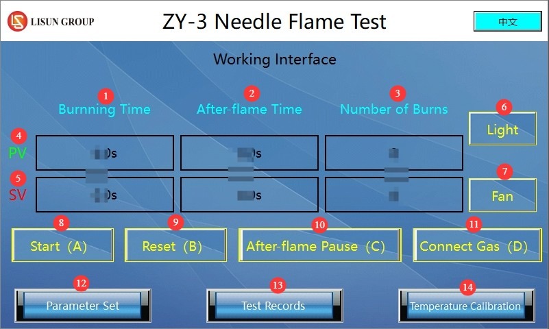
Рисунок 6
3.2 Интерфейс настройки параметров
① Burn time setting; ② Afterglow time setting; ③ Number of burns setting.
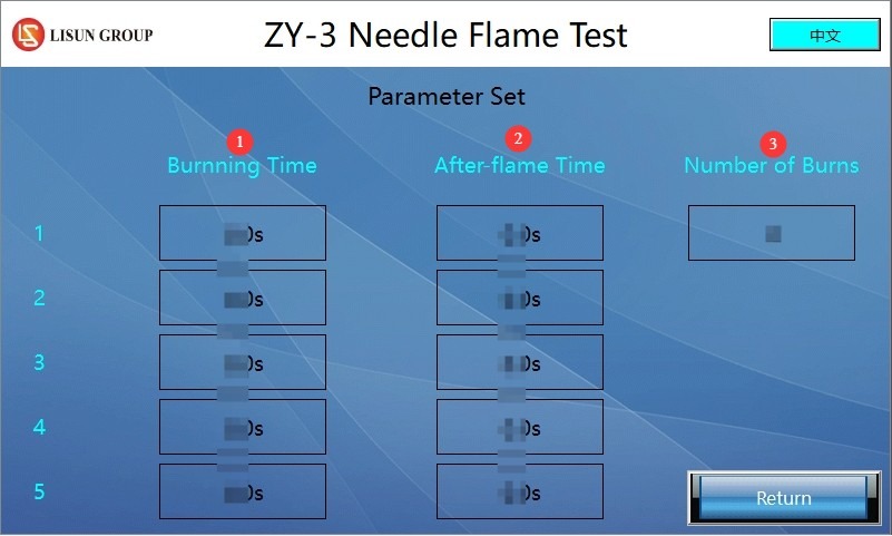
Рисунок 7
Note: If only one burn cycle is required, set the number of burn cycles to 1. If a continuous burn test is required in accordance with a specific standard (such as IEC 62368-1:2023 Annex S S.1), set the number of burn cycles according to the standard; you must also set the burn time and afterglow time separately for each burn cycle.
3.3 Интерфейс записи тестов
① Recorded burn time; ② Recorded afterglow time; ③ Reset—tap to clear the data on this page.
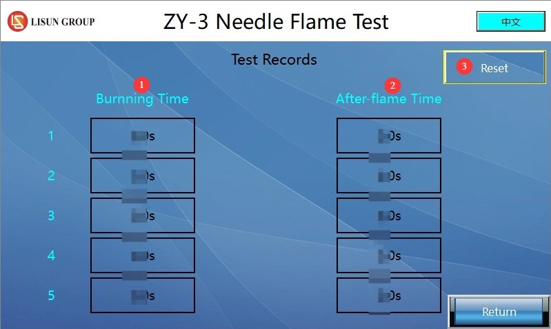
Рисунок 8
Note: Whether conducting a single-burn test or a continuous-burn test, the system automatically records the burn time and afterglow time for each burn. It can store data for up to 5 burns; once the limit is reached, you must press the reset button to clear the data before continuing to record.
3.4 Интерфейс калибровки температуры
① Отображение текущей температуры; ② Отображение времени повышения температуры; ③ Начальная настройка температуры; ④ Конечная настройка температуры; ⑤ Коррекция температуры (изменения не требуются); ⑥ Сброс: Нажмите, чтобы очистить текущие данные и повторно проверить время повышения температуры.
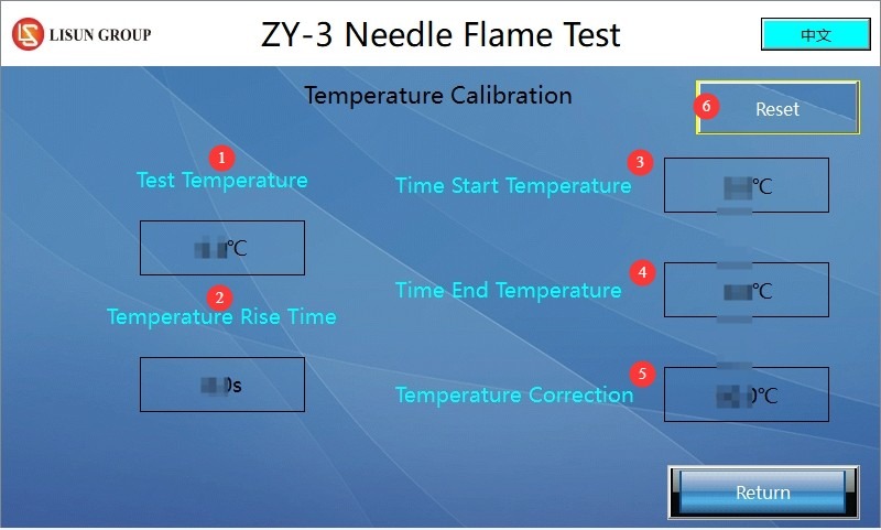
Рисунок 9
Note: Common standards (IEC 60695-11-5, IEC 60695-2-2, GB/T 5169.5, etc.) require that the starting temperature for temperature rise tests be 100°C and the ending temperature be 700°C. Users may also set other starting and ending temperatures in accordance with specific standards.
4. Подготовка к тесту
4.1 Внешняя среда
Для предотвращения влияния факторов окружающей среды на результаты испытаний установите температуру окружающей среды на уровне 23±2°C и относительную влажность на уровне 50±5%. Примечание: Требования к температуре и влажности в условиях хранения оборудования отличаются от требований к условиям его эксплуатации.
4.2 Регулировка пламени
4.2.1 Connecting the Butane Gas Supply
If you are using our standard gas supply unit, you will need to purchase a butane cylinder of the appropriate size and then connect it using the gas hose provided. ① Gas outlet on the supply unit; ② Gas inlet on the pin-flame device.
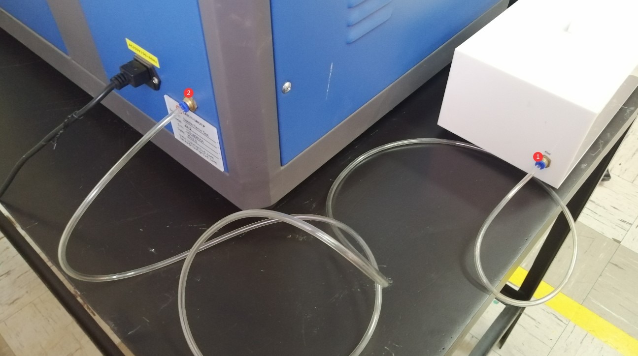
Рисунок 10
① Lock the butane cylinder; ② Turn the knob to the maximum setting.
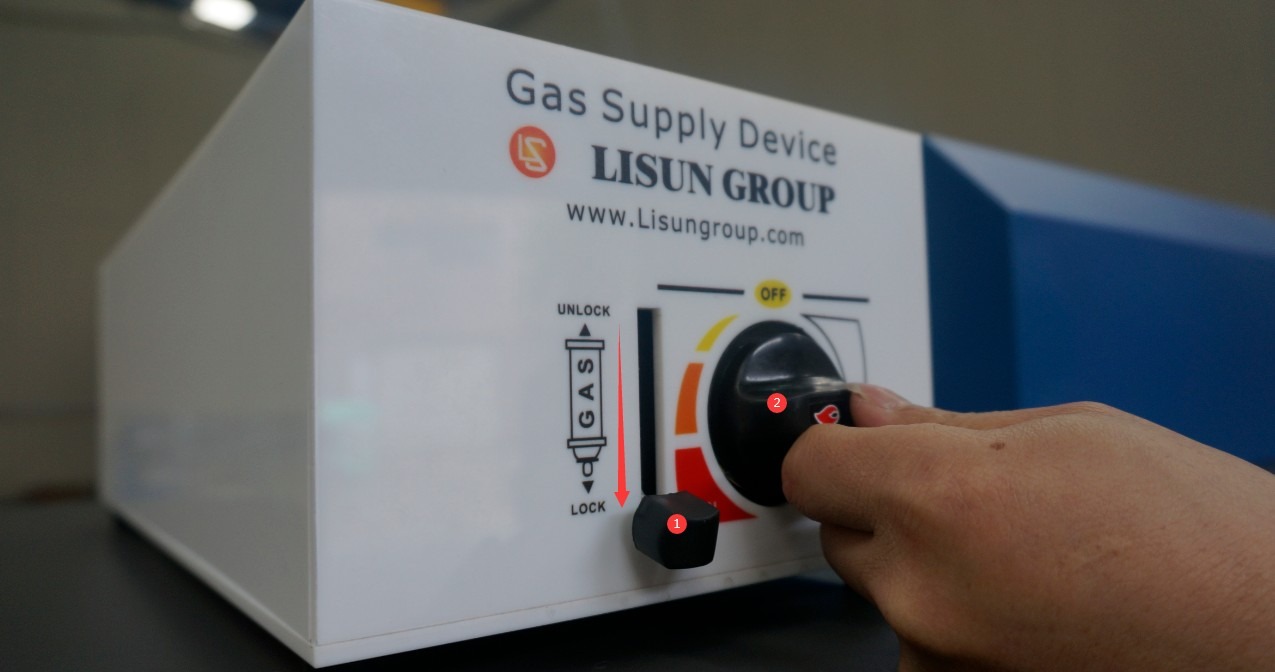
Рисунок 11
You may also use any other air supply device; simply connect it to the device’s air inlet using a 6mm-diameter air tube.
4.2.2 Регулировка пламени
Adjust the burner nozzle to a vertical position.
Access the touchscreen program interface and tap the “Gas On (D)” button.
Adjust the gas flow meter knob and use the igniter to light the wick. If the gas flow is too high or too low, the wick may not ignite; in this case, continue adjusting the gas flow while attempting to ignite the wick until the flame ignites normally. Special Note: Minimize the time interval between turning on the gas and successful ignition (less than 5 seconds); otherwise, excess gas may accumulate inside the test chamber, creating a hazard during ignition.
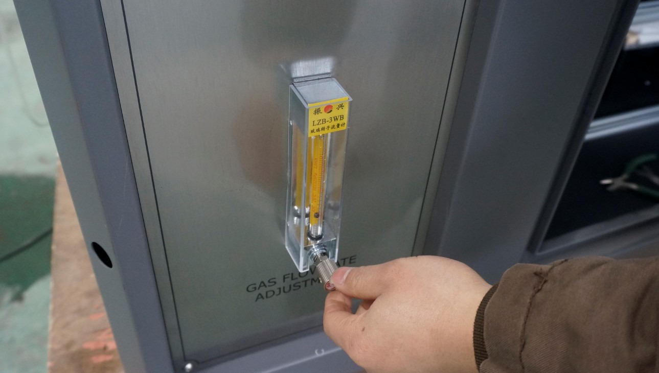
Рисунок 12
Continue adjusting the flow meter knob and use a gauge to verify that the flame height meets the standard requirements. According to the standards (IEC 60695-11-5, IEC 60695-2-2, GB/T 5169.5, etc.), the flame height should be 12 mm.
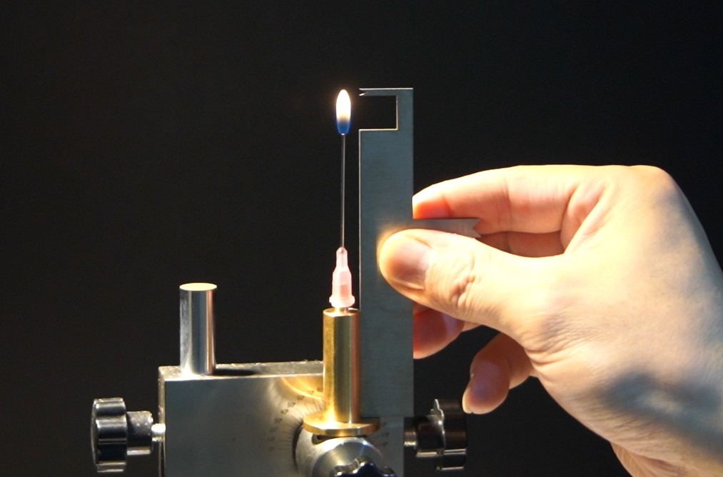
Рисунок 13
Once the flame is adjusted, there is no need to adjust the flowmeter; simply tap the “Gas On” D button on the touchscreen to shut off the gas.
4.3 Предварительная обработка образцов и их подготовка к исследованию
4.3.1 Предварительная обработка образцов
Test specimens must be complete equipment, assemblies, or components; if a portion of the specimen must be cut off, avoid exposing the cut edge to a flame.
The samples, pine boards, and silk paper should be left at 23±2°C and 50±5% relative humidity for at least 24 hours to ensure they are in a stable condition.
Remove oil, dust, and other contaminants from the sample surface to ensure that the test conditions match those of normal use.
4.3.2 Пример установки
Adjust the needle to the test angle (45°) according to the standard and secure it in place.
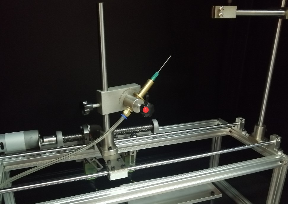
Рисунок 14
Go to the work page. Click the “Start (A)” button. The burner will automatically move to the limit stop position. At this point, secure the sample based on the position of the needle.
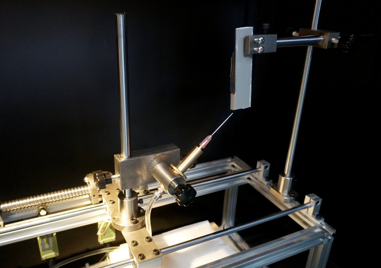
Рисунок 15
According to standard IEC 60695-11-5, the flame application positions are as follows:
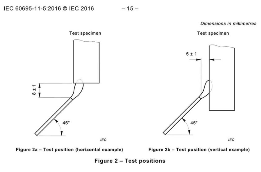
Рисунок 16
Once the sample is securely in place, click the “Reset (B)” button to return the burner to its initial position. The burner will also automatically return to its initial position once the set combustion time has elapsed. Note: You must click the “Reset (B)” button once before you can click the “Start (A)” button again.
Place the silk paper on the sample holder and position the sample holder directly below the combustion point.
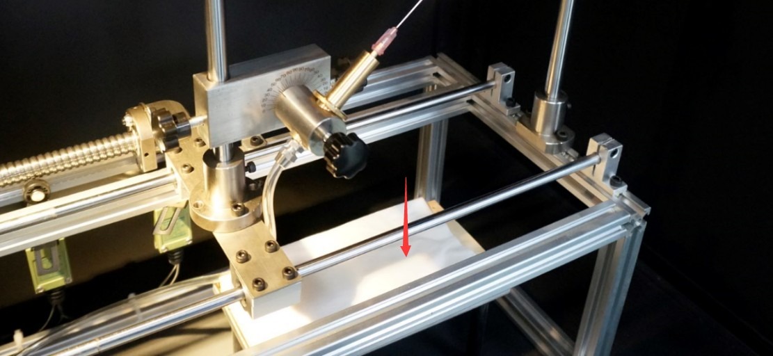
Рисунок 17
5. Needle Flame Test Procedure
5.1 Настройки параметров тестирования
Set the combustion time, afterglow time, and number of combustion cycles based on the sample properties and standard requirements.
5.2 Процедура испытаний
Press the “Gas On (D)” button on the touchscreen. Use the igniter to light the burner needle. Then close the test chamber door.
Click “Reset (B),” then click the “Start (A)” button to begin the test. The burner moves to the ignition position, and the burn time begins to be timed.
For a single combustion test: When the set combustion time ends, the afterglow time begins to be measured, the gas supply is automatically shut off, and the burner returns to its initial position. If the test specimen catches fire during the test, press the “Afterglow Pause (C)” button when the flame on the test specimen goes out to record the afterglow time.
For multiple combustion tests: At the end of the set first combustion time, the burner returns to its initial position, but the flame does not extinguish. If the sample’s flame does not extinguish within the set first afterglow time, the sample fails the test, and the gas supply is automatically shut off. If the sample’s flame extinguishes within the set first afterglow time, click “Afterglow Pause (C)” to end and record the data for the first ignition, and the burner will automatically return to the sample to start the timer for the second ignition. The third, fourth, and fifth flame application tests are conducted automatically using the same method.
6. Процедуры после испытаний
6.1 Эксплуатация оборудования после испытаний
6.1.1 Безопасное обращение
После завершения теста нажмите кнопку «Вентилятор», чтобы активировать вытяжную систему и удалить дым и токсичные газы из камеры. Подождите не менее 5 минут, пока камера проветрится, прежде чем открывать дверь.
Close the valve on the gas supply unit, unlock the gas cylinder, remove it, and store it as required (avoid direct sunlight and high temperatures, etc.).
6.1.2 Очистка оборудования
After the equipment has cooled, wipe the inner walls of the test chamber, the burner nozzle, and the sample holder with a dry cloth to remove any combustion residues.
If the silk paper or pine board has been damaged by fire, replace it immediately.
Check to see if the burner nozzle is clogged; if there are any impurities, clean it with a fine needle (taking care not to damage the nozzle orifice).
6.2 Запись и организация экспериментальных данных
Протокол испытаний должен включать следующее:
Тип образца, технические характеристики, методы подготовки и условия предварительной обработки;
Количество испытательных образцов, мест установки и точек приложения пламени;
Test parameters: burning time, afterglow time, number of tests;
Наблюдения в ходе испытаний: Воспламеняется ли образец, какова продолжительность послесвечения и полностью ли сгорел образец;
Test Results: Does it meet the flammability requirements (no ignition or afterglow ≤ 30 seconds, and the tissue paper does not ignite)?
6.3 Подготовка проб
Если образцы после анализа не сгорают полностью, их следует классифицировать и утилизировать как отходы. Если они содержат токсичные или легковоспламеняющиеся остатки, их необходимо опечатать и передать специализированному агентству для утилизации.
Сохраните часть образцов, полученных после тестирования, для последующего анализа или проверки результатов.
6.4 Хранение оборудования
6.4.1 Требования к краткосрочному хранению
Если оборудование предназначено для повседневного использования, особого обращения не требуется.
6.4.2 Требования к долговременному хранению
Если устройство не будет использоваться в течение длительного периода времени (более одного месяца), пожалуйста, отсоедините шнур питания и накройте устройство пылезащитным чехлом, чтобы предотвратить скопление пыли.
Для предотвращения износа электрических компонентов (таких как конденсаторы и контакторы) устройство следует включать раз в месяц всего на полчаса.
7. Калибровка температуры
7.1 Подготовка к калибровке
7.1.1 Условия калибровки
Ambient temperature: 23±2°C; relative humidity: 50±5%; no airflow disturbances;
The calibration copper block and thermocouple are in good condition. The copper block is made of Cu-ETP UNS C11000 and weighs 0.58 g ± 0.01 g.
7.1.2 Основа калибровки
According to the requirements of Annex A of IEC 60695-11-5 (GB/T 5169.5), the time required for the temperature of a copper block to rise from 100 °C ± 5 °C to 700 °C ± 3 °C is 23.5 s ± 1.0 s.
Процедура 7.2
Adjust the flame to 12 mm ± 1 mm using the method described in Section 4.2, then extinguish the flame.
Insert the thermocouple plug into the Omega Type K thermocouple socket provided inside the test chamber. Secure it using the standard copper block so that it is positioned 6 mm directly above the burner nozzle, ensuring that the flame fully impinges on the copper block.
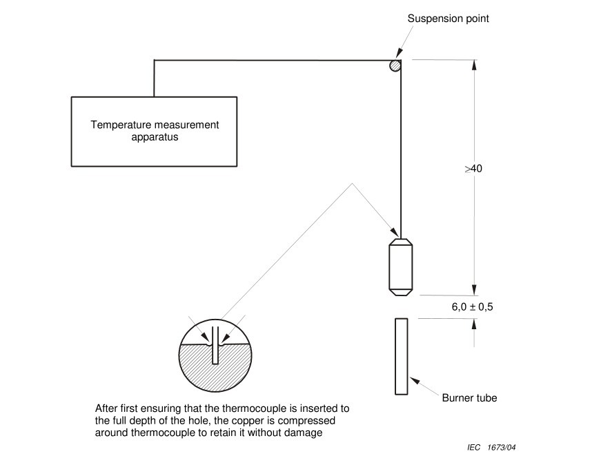
Рисунок 18
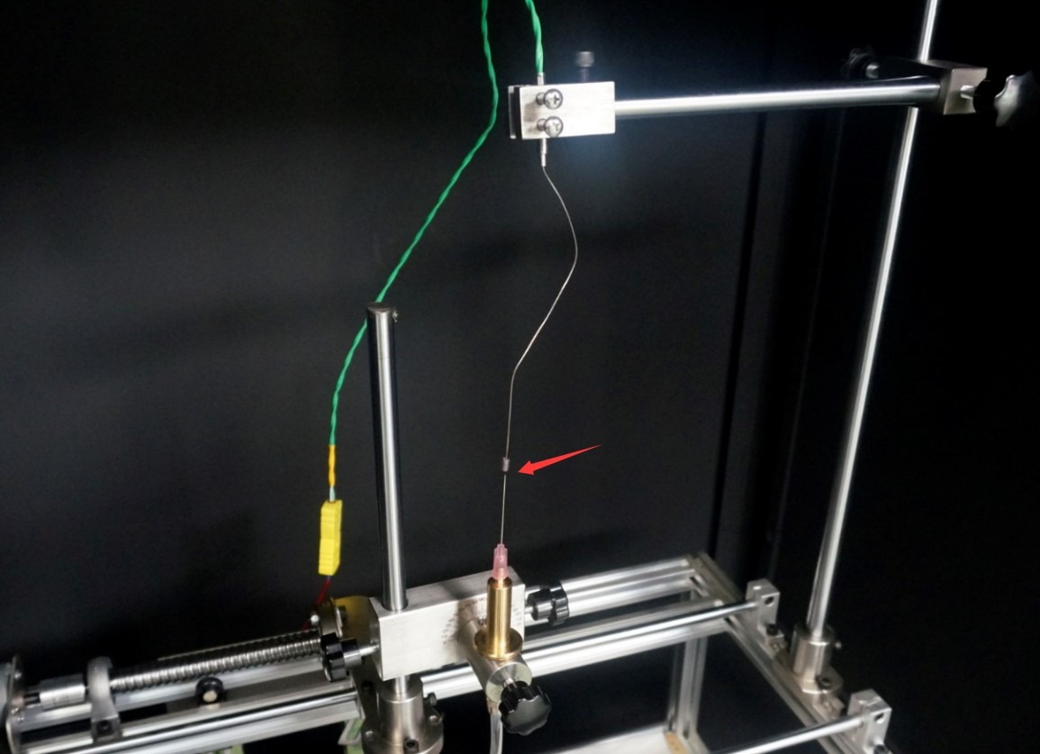
Рисунок 19
Go to the temperature calibration screen and set the following: start temperature to 100°C, end temperature to 700°C, and leave the temperature correction at the default value. Click “Reset” to clear the historical data.
Return to the work interface, click “Gas On (D),” use the igniter to light the burner, and slowly close the test chamber door.
Вернитесь к экрану калибровки температуры и обратите внимание на текущую температуру и время нагрева, отображаемые на сенсорном экране. Таймер запускается автоматически, когда медный блок достигает 100 °C, и автоматически останавливается, когда он достигает 700 °C.
Повторите калибровку три раза, давая медному блоку остыть естественным образом до температуры ниже 50 °C после каждого измерения.
Calculate the average time to temperature rise based on the three measurements; if it is within 23.5 s ± 1.0 s, the flame meets the requirements.
7.3 Handling Temperature Deviations During Calibration
The temperature rise time is used to determine whether the butane gas you are using, the flame being calibrated, and the test conditions meet the standard test requirements. If the temperature rise time is incorrect, it means your test does not meet the standard requirements; it does not indicate a problem with the equipment itself.
8. Текущее обслуживание
| Цикл обслуживания | Проекты технического обслуживания | Операции по техническому обслуживанию |
| После каждого теста | Очистка оборудования | 1. Wipe down the interior and exterior of the test chamber, the observation window, and the fixtures; 2. Clean up any drips and soot from the sample tray. |
| Раз в неделю | Обслуживание подшипников | Wipe down the linear bearing rail with a cloth dampened with mineral oil to ensure the moving parts operate smoothly. |
| Раз в месяц | Проверка газовой системы | 1. Check the gas connection for leaks (using soapy water); 2. Inspect the hoses for signs of aging and replace them if necessary; |
| Раз в 3 месяца | Калибровка пламени | Flame temperature rise test to verify whether the temperature rise time complies with 23.5 ± 1 s |
| Раз в 6 месяца | Осмотр электрической системы | 1. Убедитесь в надежности подключения силовых проводов и клемм заземления; 2. Замените изношенные предохранители; 3. Проверьте работоспособность системы зажигания. |
| Раз в год | Комплексное обслуживание | 1. Replace the gas hoses and gaskets; 2. Calibrate the touchscreen’s timing accuracy; 3. Inspect the needles for wear and replace them if necessary; 4. Contact the supplier to arrange for professional testing and calibration |
9. Поиск и устранение распространенных проблем
9.1 The flame won’t ignite
| Признаки неисправности | Возможные причины | Метод |
| No flame during ignition | 1. The valve on the gas supply unit is not open; 2. There is a leak in the gas line; 3. The needle is clogged; 4. The igniter is malfunctioning | 1. Open the gas supply valve and make sure there is sufficient gas; 2. Check the pipe connections, tighten any loose parts, and use soapy water to check for leaks; 3. Use a fine needle to remove debris from the needle tip, or replace it with a spare needle; 4. Replace the igniter battery, or replace the igniter with a spare one |
| Gas is escaping, but it won’t ignite | 1. Insufficient gas purity; 2. Excessive gas buildup inside the test chamber; 3. The igniter is too far from the needle | 1. Replace the butane/propane gas with a purity of ≥95%; 2. Open the chamber door to ventilate for 5–10 minutes before igniting; 3. Adjust the position of the igniter so that it is close to the tip of the needle when igniting. |
9.2 Temperature Calibration Failed
| Признаки неисправности | Возможные причины | Метод |
| The warm-up time is too long | 1. Insufficient flame height; 2. Gas flow rate too low; 3. Copper block misaligned | 1. Readjust the flame height to 12 mm ± 1 mm; 2. Turn the gas flow meter knob clockwise to increase the gas flow rate; 3. Adjust the position of the copper block to ensure it is 6 mm directly above the needle tip. |
| The warm-up time is too short | 1. Flame height exceeds the limit; 2. Gas flow rate is too high | 1. Reduce the gas flow rate and use a gauge to calibrate the flame height; 2. Fine-tune the flow meter knob to reduce the gas supply intensity. |
| Нет отображения температуры | 1. The thermocouple is not connected properly; 2. The thermocouple is damaged | 1. Unplug and replug the thermocouple connector to ensure a secure connection; 2. Replace the thermocouple with a new one. |
9.3 Afterglow duration cannot be recorded
| Признаки неисправности | Возможные причины | Метод |
| After the sample flame goes out, clicking “Afterglow Pause” produces no response. | 1. The “Start” button was not pressed first; 2. The “Afterglow Pause” button was not reset; 3. Touchscreen malfunction | 1. Verify that the test has started and the burn time has elapsed; 2. Press the “Afterglow Pause” button to reset the system before proceeding; 3. Restart the device; if the problem persists, contact customer service. |
9.4 The Device Will Not Start
| Признаки неисправности | Возможные причины | Метод |
| The touchscreen does not respond after the power is turned on | 1. The power cord is not properly connected; 2. The power supply voltage is abnormal; 3. The fuse has blown | 1. Check the power cord connection and make sure the plug is securely inserted; 2. Verify that the power supply voltage is 220V ± 10%; 3. Replace the fuse with one of the same specification (included in the packing list). |