
 Английский
 中文简体
中文简体 Русский
 Español
 Português
 Türkçe
 العربية
 Deutsch
 Polski
 Italiano
 Français
 한국어
한국어 ไทย
ไทย Tiếng Việt
 日本語
日本語





























Тестер поврежден проводом
Руководство пользователя
Применимый LISUN модели: WDT-1,WDT-1А.WDT-1B
1. Базовое понимание оборудования
1.1 Назначение оборудования
The WDT Series Wire Damaged Tester is used to evaluate the ability of threaded and threadless terminal blocks to withstand mechanical stress under normal operating conditions, and to assess whether the structural design of the terminal blocks meets safety requirements by ensuring that no excessive damage is inflicted on the wire during clamping.
The equipment simulates the combined mechanical stresses—including torsion and tensile forces—that wires experience during the actual assembly and use of terminals. After completing a specified number of rotation cycles, the extent of wire damage is inspected. It is suitable for type testing of plugs and sockets, wall switches, and low-voltage connector electrical accessories.
1.2 Applicable Test Samples and Wire Types
Образцы для испытаний: Terminals for plugs and receptacles for household and similar uses; terminals for fixed switches; threaded and non-threaded clamping connectors for low-voltage circuits;
Тестовые кабели: Class 1 rigid single-conductor cable; Class 2 rigid stranded cable; Class 5 flexible cable (multi-strand flexible cable).
1.3 Model Classification and Applicable Standards
This equipment complies with numerous domestic and international standards; testing must be conducted in strict accordance with the relevant provisions of those standards:
| LISUN Модель | WDT-1 | WDT-1A | WDT-1B | ||
|---|---|---|---|---|---|
| Control and Operation Methods | сенсорный экран управления Операции | ||||
| Рабочая станция | Одностанционная | ||||
| Рабочая скорость | 5–12 revolutions per minute | ||||
| Диаметр вращения | 75 мм | 75 мм, 76 мм | |||
| Продолжительность теста | 0–99 min 59 s | ||||
| Количество циклов испытаний | Adjustable from 0 to 999999 times | ||||
| Массы | 0.3, 0.4, 0.7, 0.9, 1.4, 2.0 кг | 0.2, 0.3, 0.4, 0.7, 0.9, 1.4, 2.0, 2.9, 4.5, 6.8 кг | 0.3, 0.4, 0.7, 0.9, 1.4, 2.0, 2.3, 3.6, 4.5, 6.8, 8.2, 11.4, 13.6, 18.2, 22.7, 27.2, 36.3,45.4 кг | ||
| Высота Расстояние | Регулируется от 240 до 300 мм | Регулируется от 240 до 640 мм | |||
| Диаметр корпуса | 6.5, 9.5 мм | 6.4, 6.5, 9.5, 13, 14.5 мм | 6.5–31.8 mm, 13 in total | ||
| Height Adjustment Methods | Ручная регулировка | Автоматическая регулировка | |||
| Применимые стандарты | GB/T 2099.1, пункт 12.2.5 и рисунок 11 (IEC 60884-1, Clause 12.2.5 and Figure 13) | GB/T 13140.3, Clause 10.105 and Figure 101 (IEC 60998-2-2, Clause 10.105 and Figure 101), GB/T 16915.1, Clause 12.5 and Figure 9 (IEC 60699-1, Clause 12.2 and Figure 9) | GB/T 2099.1, пункт 12.2.5 и рисунок 11 (IEC 60884-1, Clause 12.2.5 and Figure 11), GB/T 16915.1, Clause 12.2.5 and Figure 10 (IEC 60669-1, Clause 12.2.5 and Figure 10), UL 486A-B, Clause 9.3.2, Table 26, and Figure 4 | ||
Примечание: В данном руководстве используется WDT-1 as an example; the operating principles are the same for other models.
1.4 Operating Principle of the Equipment
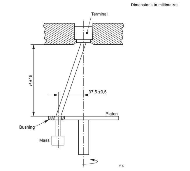
The terminal under test is secured to a rotating turntable; the wire is threaded through the hole in the guide sleeve, and a standard weight is suspended from its lower end to apply vertical tensile force; A motor drives the turntable to rotate at a set speed, simulating the mechanical stress caused by repeated twisting of the wire within the terminal; after the preset time has elapsed, the equipment automatically stops and sounds an alarm, after which the damage to the wire is assessed in accordance with standard requirements.
2. Меры предосторожности при использовании
2.1 Environmental Safety Precautions
Place the equipment on a level and stable test bench, leaving at least 30 cm of space on all sides for heat dissipation;
Ambient temperature: 10–35°C; no corrosive gases; no excessive dust;
The power outlet must be properly grounded; under no circumstances should the device be turned on without being grounded. The power supply voltage must be stable at 220 V AC ±10%.
2.2 Меры предосторожности перед началом работы
Operators must read the entire instruction manual before operating the equipment; untrained personnel are prohibited from operating the equipment on their own;
Do not reach into the rotating area under any circumstances; do not touch the turntable or the weight assembly while the equipment is in operation;
Never overload the weights, and do not use weights not designed for this machine.
2.3 Safety Precautions During the Test Procedure
If wire breaks, the sample becomes loose, or there are unusual noises or odors during the test, immediately press the emergency stop button to cut off the power;
Do not adjust the height, replace the sleeve, or install or remove test specimens while the equipment is in operation;
For prolonged continuous operation, it is recommended to shut down the machine for at least 30 minutes every 4 hours to allow the motor to cool.
3. Обзор оборудования
3.1 Стандартная диаграмма
See Figure 3-1 (using Figure 13 of IEC 60884-1 Например).
3.2 WDT-1 Обзор продукта
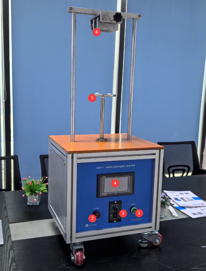
3.2.1 Внешний вид оборудования
См. Рисунок 3-2.
| Номер регистрации | Внимание |
|---|---|
| ① | Выключатель |
| ② | Buzzer—sounds an alarm when the test is complete |
| ③ | Motor switch and motor speed control knob. Note: The motor switch should be set to the “always on” position; the touchscreen program automatically controls the motor’s start and stop. In the event of an emergency, the motor switch can be turned off directly to cut off power to the motor. |
| ④ | сенсорный экран |
| ⑤ | WDT-1 rotary table includes two types of sleeve hole diameters: 6.5 mm and 9.5 mm. For other models, please refer to the corresponding standards. |
| ⑥ | Terminal Clamp, Height-Adjustable |
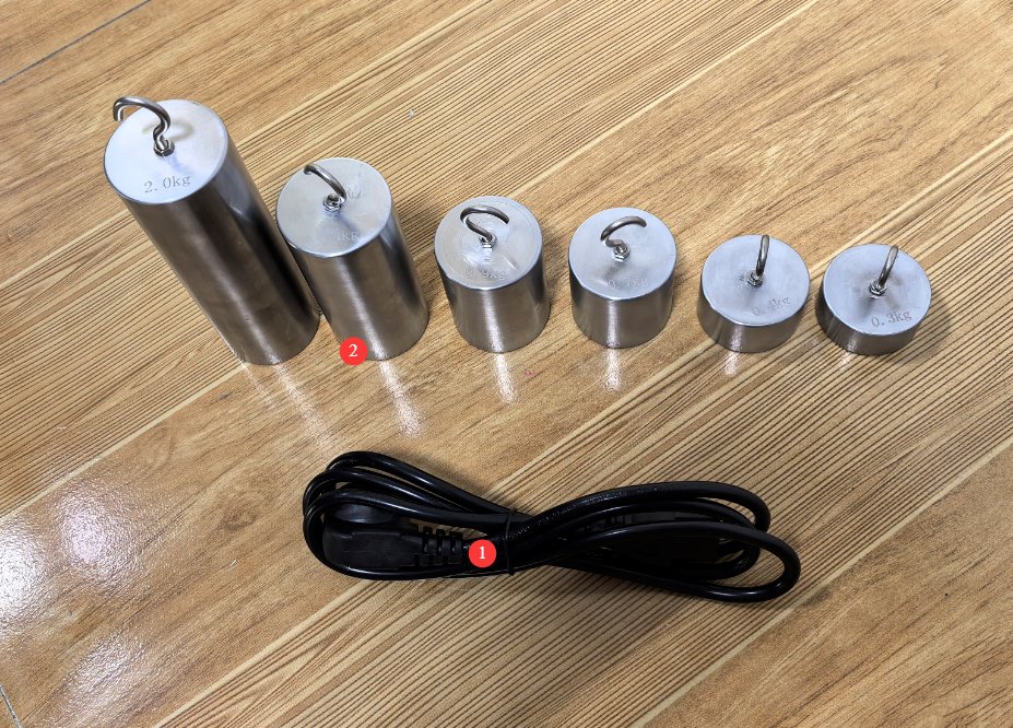
3.2.2 Основные компоненты
См. Рисунок 3-3.
| Номер регистрации | Внимание |
|---|---|
| ① | Шнур питания |
| ② | Weights: The WDT-1 набор включает в себя six weights: 0.3, 0.4, 0.7, 0.9, 1.4, and 2.0 kg. For other models, please refer to the corresponding standards. |
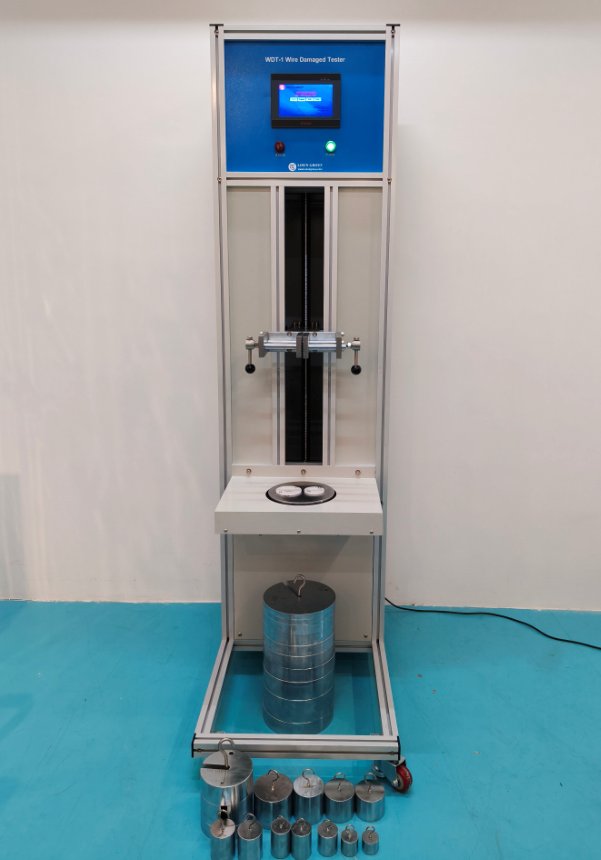
3.3 Introduction to Other Models
Wire Damaged Testers containing heavier weights, such as the WDT-1B, are large, floor-standing units, as shown in Figure 3-4. Their operating principles are the same as those of the WDT-1.
4. Введение в программу сенсорного экрана
4.1 Начальный экран
См. Рисунок 4-1.
| Номер регистрации | Внимание |
|---|---|
| ① | Chinese test interface for conducting wire damage severity tests |
| ② | English test interface for conducting wire damage severity tests |

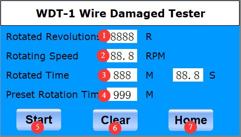
4.2 Тестовый интерфейс
См. Рисунок 4-2.
| Номер регистрации | Внимание |
|---|---|
| ① | Number of Revolutions Displayed |
| ② | Display of the current turntable rotation speed. Taking IEC 60884-1 as an example, the turntable speed during the test should be 10 ± 2 RPM. If there is a deviation, slowly adjust the motor speed control knob. For other standards, please refer to the specific standard requirements. |
| ③ | Rotation Duration Display |
| ④ | Set the test duration; for example, according to IEC 60884-1, set it to 15 minutes. For other standards, please refer to the specific requirements of each standard. |
| ⑤ | Начать/остановить тест |
| ⑥ | Reset the test data; you must reset the data from the previous test before starting a new one. |
| ⑦ | Вернуться на главный экран |
5. Conductor Damage Program Test
5.1 Тестовая процедура
Take Clause 12.2.5 of IEC 60884-1 as an example. For other standards, refer to the specific requirements of the corresponding standard.
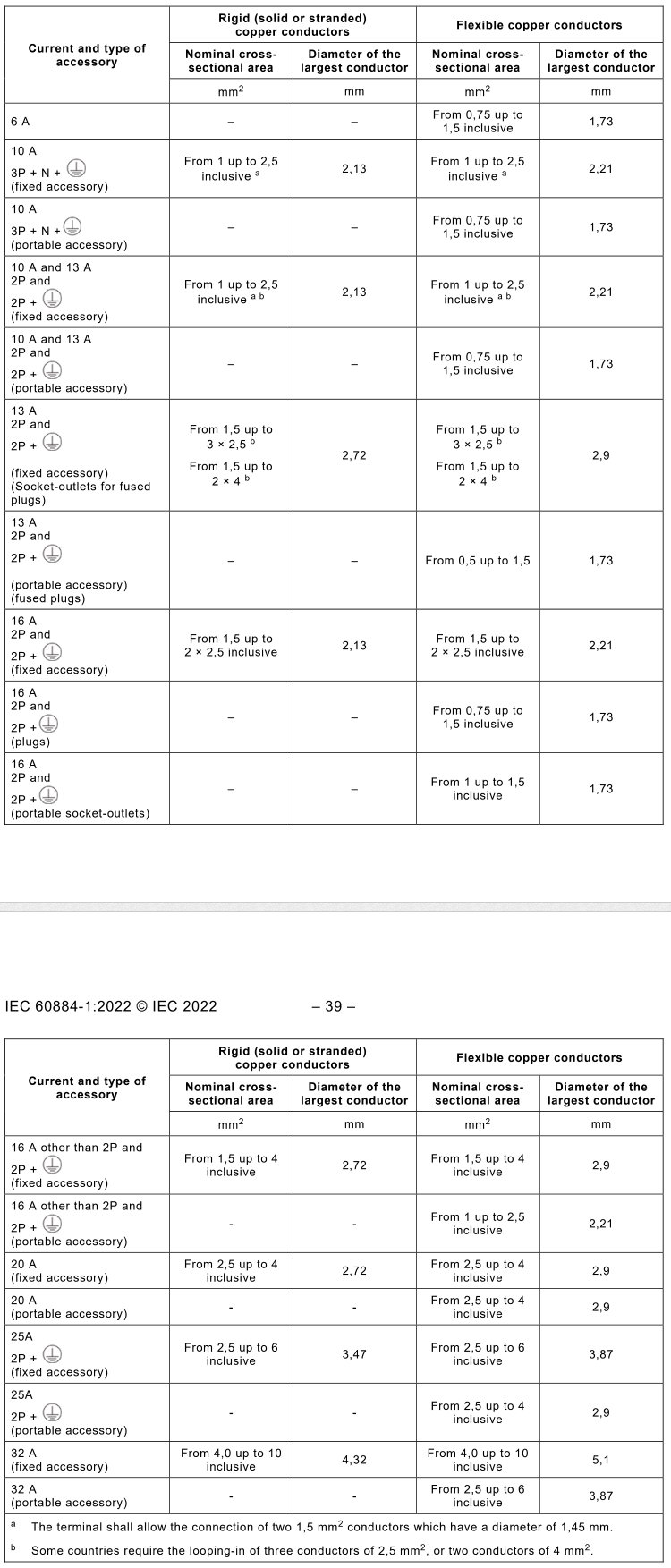
Place the terminals in the test setup as described in 3.1, and install rigid solid conductors, rigid stranded conductors, and/or flexible conductors in sequence as shown in Figure 5-1 (taken from Table 4 of IEC 60884-1), starting with the conductor having the smallest nominal cross-sectional area and proceeding to the one with the largest.
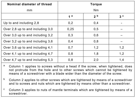
Then, tighten the clamping screws or nuts to the torque specified in Figure 5-2 (taken from Table 7 of IEC 60884-1).
As shown in Figure 5-1, terminals suitable for both rigid and flexible conductors were tested using rigid solid conductors, rigid stranded conductors, and a set of new flexible conductor specimens.
Terminals designed exclusively for flexible conductors (rewireable portable accessories) must be tested using flexible conductors.
The length of the test conductor shall be 75 mm longer than the height (H) specified in Figure 5-3 (taken from Table 10 of IEC 60884-1).
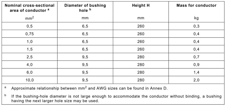
The end of the conductor is passed through the appropriate bushing hole in the turntable at a height (H) below the terminal; this height is also specified in Figure 5-3. The bushing hole shall be positioned on a horizontal plane such that its centerline describes a circle with a diameter of 75 mm, the center of which shall be aligned vertically with the terminal; the turntable shall then be rotated at a speed of 10 ± 2 revolutions per minute.
The distance between the opening of the terminal clamp and the upper surface of the bushing hole shall be within ±15 mm of the height specified in Figure 5-3. The bushing hole may be lubricated to prevent the insulated conductor from jamming, twisting, or rotating.
Hang a weight of the mass specified in Figure 5-3 from the end of the conductor. The test lasts 15 minutes.
5.2 Оценка результатов испытаний
The wire must not slip out of the terminal clamping device; the wire must not break at the clamping terminal; the extent of wire damage must not render it “unfit for further use”; Test using Grade 5 multi-strand flexible wire: A small number of copper strands may break, but the number of broken strands must not exceed 15% of the total number of strands in the wire; if it exceeds 15%, the sample is deemed unqualified.
6. Ежедневное техническое обслуживание и уход за оборудованием.
Daily Maintenance After Use
Turn off the main power to the equipment; wipe down the equipment housing, turntable, and clamps with a dry, soft cloth, and remove any scattered copper wire debris; do not rinse the equipment directly with liquid; wipe the weights clean and return them to their storage location, taking care to avoid bumps or scratches.
6.2 Еженедельное обслуживание
Inspect the lead screw and guide rails, and remove any dust; apply a small amount of rust-preventive grease; check all fastening screws, as well as the turntable clamps and bracket lock nuts, for looseness, and tighten them promptly; perform a no-load test run for 30–50 revolutions to verify that the rotational speed is stable and the count is accurate.
6.3 Ежемесячное обслуживание
Inspect the appearance of the weights to ensure that the weight markings are intact and that there are no significant dents or deformations; check that the sleeve holes are free of cracks and wear, and replace any damaged parts promptly.
Долгосрочное хранение и техническое обслуживание
6.4.1 Pre-treatment Before Storage
Thoroughly clean and dry the equipment, and apply rust-preventive oil to all metal surfaces; pack and store weights and other accessories separately to prevent damage from bumping; cover the entire unit with a dust cover for protection.
6.4.2 Требования к условиям хранения
Хранить в помещении, в сухом, хорошо проветриваемом месте, свободном от коррозионных газов; температура окружающей среды должна быть от 5°C до 35°C, а относительная влажность не должна превышать 80%; хранить оборудование в горизонтальном положении, чтобы предотвратить деформацию, вызванную сильным давлением.
6.5 Требования к интервалу калибровки
Для обеспечения точности и надежности устройства рекомендуется периодически отправлять его на калибровку в квалифицированную независимую метрологическую лабораторию. Рекомендуемый интервал калибровки составляет 12 месяцев. Пользователи могут определить конкретный интервал калибровки в зависимости от частоты использования, условий окружающей среды и требований системы качества.
7. Поиск и устранение распространенных проблем
7.1 The device does not respond when powered on, and the screen does not light up
| Признаки неисправности | Действия по устранению неполадок | Метод |
|---|---|---|
| No display on the startup screen; the entire unit shows no signs of operation. | 1. Check the power cord and ensure the outlet is supplying 220 V AC power; 2. Check the device’s power switch; 3. Check the device’s fuse. | 1. Restore power; 2. Make sure the switch is set to ON; 3. Replace the fuse with one of the same specification; if it keeps blowing, contact customer service. |
7.2 After completing the parameter settings, press “Start,” but the turntable does not rotate.
| Признаки неисправности | Действия по устранению неполадок | Метод |
|---|---|---|
| Click to start, but the wheel doesn’t move | 1. Check the motor switch and speed control knob; 2. Check the test duration setting; | 1. Make sure the motor switch is turned on and the speed control knob is not set to the lowest position; 2. Make sure the test duration is set correctly |
7.3 Unusual noises and excessive vibration during operation
| Признаки неисправности | Действия по устранению неполадок | Метод |
|---|---|---|
| Loud noise and vibration during rotation | 1. Check whether the sample in the turntable fixture is not securely fastened; 2. The nut on the lifting lead screw is loose; 3. The weights are rattling and colliding with the bracket. | 1. Retighten the test specimen; 2. Tighten all securing nuts; 3. Adjust the weights to ensure the specimen hangs vertically. |
7.4 The touchscreen is unresponsive; tapping does not produce a response
| Признаки неисправности | Действия по устранению неполадок | Метод |
|---|---|---|
| Touch and tap not responding | 1. Turn off the power and restart the device; 2. There is grease on the screen surface | 1. Unplug the device and restart it to reset it; 2. Wipe the screen with a soft cloth; if the problem persists, contact customer service. |
7.5 Severe oscillation of the weights, resulting in test interference
| Признаки неисправности | Действия по устранению неполадок | Метод |
|---|---|---|
| The weight swings widely | 1. The sample is not centered; 2. The height is not adjusted correctly; 3. The sleeve is not compatible with the wire. | 1. Reinstall the terminals to ensure they are aligned; 2. Adjust the height of the clamping fixture; 3. Replace the sleeve with the corresponding inner diameter. |